Infiniti FX35 / FX45. Manual — part 814
INTERIOR ROOM LAMP
LT-151
< SERVICE INFORMATION >
C
D
E
F
G
H
I
J
L
M
A
B
LT
N
O
P
TKWM4319E
LT-152
< SERVICE INFORMATION >
INTERIOR ROOM LAMP
TKWM4320E
INTERIOR ROOM LAMP
LT-153
< SERVICE INFORMATION >
C
D
E
F
G
H
I
J
L
M
A
B
LT
N
O
P
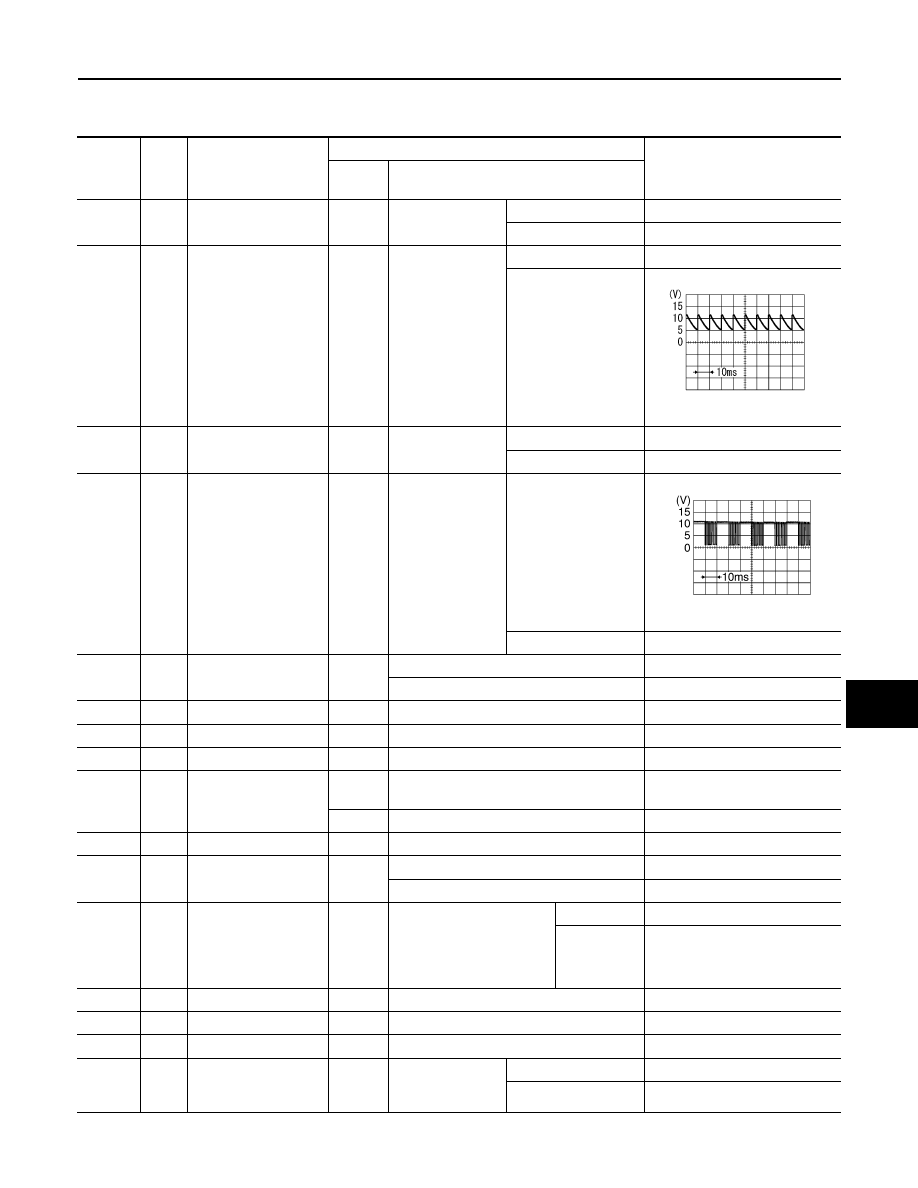
Terminal and Reference Value for BCM
INFOID:0000000001328410
Terminal
No.
Wire
color
Signal name
Measuring condition
Reference value
Ignition
switch
Operation or condition
1
PU
Ignition keyhole illumi-
nation signal
OFF
Ignition keyhole
illumination
Illuminated
Battery voltage
Not illuminated
Approx. 0 V
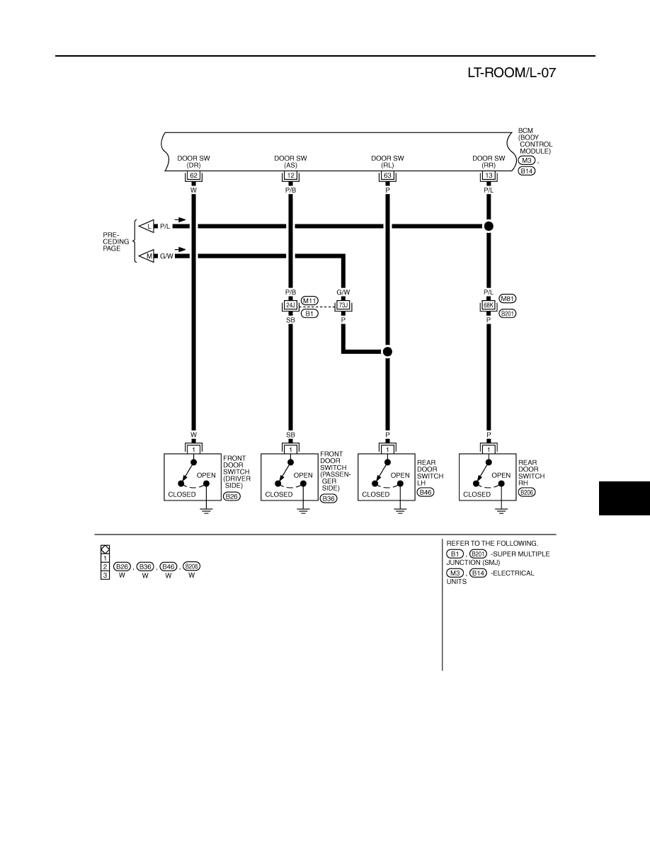
12
P/B
Front door switch (pas-
senger) signal
OFF
Front door switch
(passenger side)
ON (open)
Approx. 0 V
OFF (closed)
Approx. 7.5 - 8.0 V
13
P/L
Rear door switch RH
signal
OFF
Rear door switch
RH
ON (open)
Approx. 0 V
OFF (closed)
Battery voltage
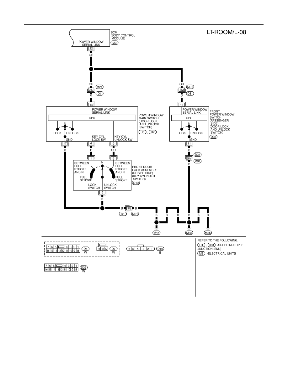
22
OR
Power window switch
serial link
—
Power window
main switch (door
lock and unlock
switch) and power
window sub-
switch (front pas-
senger side) (door
lock and unlock
switch)
Lock or unlock switch
ON
NOTE:
Approx. 10 seconds
after door lock and un-
lock switch (driver side
and passenger side) is
turned “LOCK” or “UN-
LOCK”.
Approx. 9.0 - 9.5 V
OFF
Battery voltage
37
B/W
Key-in detection switch
signal
OFF
Vehicle key is removed.
Approx. 0 V
Vehicle key is inserted.
Battery voltage
38
W/L
Ignition power supply
ON
—
Battery voltage
39
L
CAN
−
H
—
—
—
40
P
CAN
−
L
—
—
—
41
R/B
Battery saver output
signal
OFF
30 minutes after ignition switch is turned to
OFF
Approx. 0 V
ON
—
Battery voltage
42
L/R
Battery power supply
OFF
—
Battery voltage
47
Y/R
Step lamp signal
OFF
Any door is open (ON)
Approx. 0 V
All doors are closed (OFF)
Battery voltage
48
PU/W
Interior room lamp,
map lamp, front door
inside handle and rear
door inside handle illu-
mination output signal
OFF
Any door switch
ON (open)
Approx. 0 V
OFF (closed)
Battery voltage
49
B
Ground
ON
—
Approx. 0 V
52
B
Ground
ON
—
Approx. 0 V
55
G
Battery power supply
OFF
—
Battery voltage
58
L
Back door switch sig-
nal
OFF
Back door closure
motor (door
switch)
ON (open)
Approx. 0 V
OFF (closed)
Battery voltage
SKIB3419J
PKIC0930E
LT-154
< SERVICE INFORMATION >
INTERIOR ROOM LAMP
How to Proceed with Trouble Diagnosis
INFOID:0000000001328411
1.
Confirm the symptom or customer complaint.
2.
Understand operation description and function description. Refer to
.
3.
Perform Preliminary Check. Refer to
.
4.
Check symptom and repair or replace the cause of malfunction.
5.
Does interior room lamp operate normally? If YES, GO TO 6. If NO, GO TO 4.
6.
INSPECTION END
Preliminary Check
INFOID:0000000001328412
CHECK FOR POWER SUPPLY AND GROUND CIRCUIT
1.
CHECK FUSES
Check for blown fuses.
Refer to
LT-145, "Wiring Diagram - ROOM/L -"
.
OK or NG
OK
>> GO TO 2.
NG
>> If fuse is blown, be sure to eliminate cause of malfunction before installing new fuse. Refer to
2.
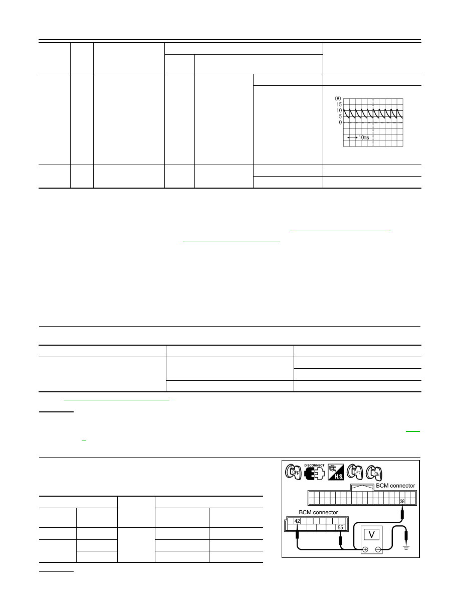
CHECK POWER SUPPLY CIRCUIT
1.
Turn ignition switch OFF.
2.
Disconnect BCM connector.
3.
Check voltage between BCM harness connector and ground.
OK or NG
62
W
Front door switch (driv-
er side) signal
OFF
Front door switch
(driver side)
ON (open)
Approx. 0 V
OFF (closed)
Approx. 7.0 - 7.5 V
63
P
Rear door switch LH
signal
OFF
Rear door switch
LH
ON (open)
Approx. 0 V
OFF (closed)
Battery voltage
Terminal
No.
Wire
color
Signal name
Measuring condition
Reference value
Ignition
switch
Operation or condition
PKIB4960J
Unit
Power source
Fuse and fusible link No.
BCM
Battery
M
22
Ignition switch ON or START position
1
(+)
(-)
Ignition switch position
BCM con-
nector
Terminal
OFF
ON
M3
38
Ground
Approx. 0 V
Battery voltage
M4
42
Battery voltage
Battery voltage
55
Battery voltage
Battery voltage
PKIA7520E
Нет комментариевНе стесняйтесь поделиться с нами вашим ценным мнением.
Текст