Infiniti FX35 / FX45. Manual — part 815
INTERIOR ROOM LAMP
LT-155
< SERVICE INFORMATION >
C
D
E
F
G
H
I
J
L
M
A
B
LT
N
O
P
OK
>> GO TO 3.
NG
>> Repair harness or connector.
3.
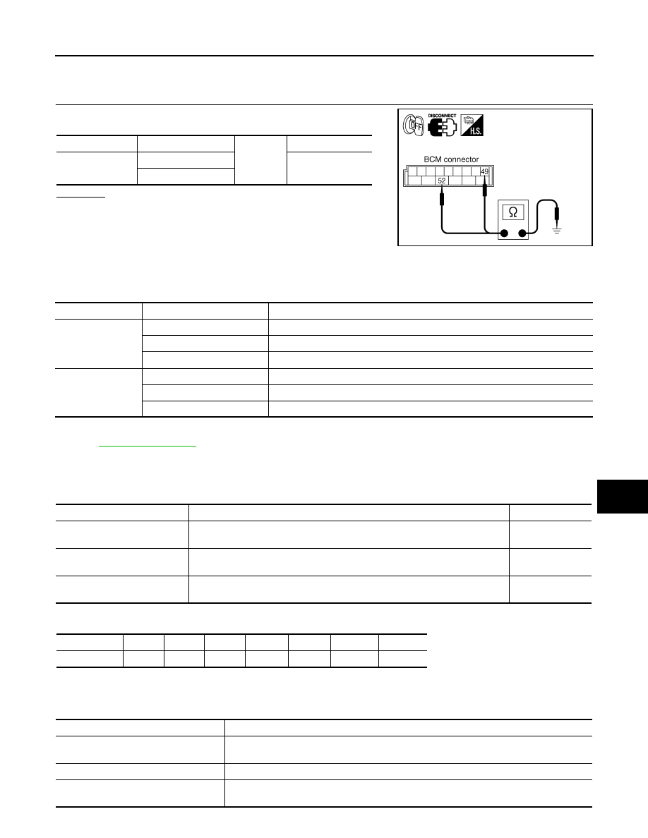
CHECK GROUND CIRCUIT
Check continuity between BCM harness connector and ground.
OK or NG
OK
>> INSPECTION END
NG
>> Repair harness or connector.
CONSULT-III Functions (BCM)
INFOID:0000000001328413
CONSULT-III can display each diagnostic item using the diagnostic test mode shown following.
CONSULT-III BASIC OPERATION
.
WORK SUPPORT (INT LAMP)
Display Item List
Reference between “MODE” and “TIME” for “TURN ON/OFF”
DATA MONITOR (INT LAMP)
Display Item List
BCM connector
Terminal
Ground
Continuity
M4
49
Yes
52
SKIA5294E
BCM diagnosis part
Diagnosis mode
Description
INT LAMP
WORK SUPPORT
Changes setting for each function.
DATA MONITOR
Displays BCM input data in real time.
ACTIVE TEST
Operation of electrical loads can be checked by sending driving signal to them.
BATTERY SAVER
WORK SUPPORT
Changes the setting for each function.
DATA MONITOR
Displays BCM input data in real time.
ACTIVE TEST
Operation of electrical loads can be checked by sending driving signal to them.
Item
Description
CONSULT-III
SET I/L D
−
UNLCK INTCON
The 30 seconds glowing function interior room lamps and ignition keyhole illu-
mination can be selected when driver door is released (unlocked).
ON/OFF
ROOM LAMP ON TIME SET
The time in order to escalate illumination can be adjusted when interior room
lamps and ignition keyhole illumination is turned on.
MODE 1 – 7
ROOM LAMP OFF TIME SET
The time in order to diminish illumination can be adjusted when interior room
lamps and ignition keyhole illumination is turned off.
MODE 1 – 7
MODE
1
2
3
4
5
6
7
Time (sec.)
0.5
1
2
3
4
5
0
Monitor item
Contents
IGN ON SW
“ON/OFF”
Displays “IGN position (ON)/OFF, ACC position (OFF)” judged from the ignition switch sig-
nal.
KEY ON SW
“ON/OFF”
Displays “Key inserted (ON)/key removed (OFF)” status judged from the key switch signal.
DOOR SW - DR
“ON/OFF”
Displays status of the driver door as judged from the driver door switch signal. (Door is open:
ON/Door is closed: OFF)

LT-156
< SERVICE INFORMATION >
INTERIOR ROOM LAMP
NOTE:
• 1: Vehicle with Intelligent Key system display this item.
• 2: Vehicle with remote keyless entry system display this item.
ACTIVE TEST (INT LAMP)
Display Item List
NOTE:
This item is displayed, but cannot be tested.
WORK SUPPORT (BATTERY SAVER)
Display Item List
DATA MONITOR (BATTERY SAVER)
Display Item List
DOOR SW - AS
“ON/OFF”
Displays status of the passenger door as judged from passenger door switch signal. (Door
open (ON)/Door closed (OFF))
DOOR SW - RR
“ON/OFF”
Displays status of rear door as judged from the rear door switch (RH) signal. (Door is open:
ON/Door is closed: OFF)
DOOR SW - RL
“ON/OFF”
Displays status of rear door as judged from the rear door switch (LH) signal. (Door is open:
ON/Door is closed: OFF)
BACK DOOR SW
“ON/OFF”
Displays status of the back door as judged from back door switch signal. (Door open (ON)/
Door closed (OFF))
KEY CYL LK - SW
“ON/OFF”
Displays “Door locked (ON) status, determined from key cylinder lock switch in driver door.
KEY CYL UN - SW
“ON/OFF”
Displays “Door unlocked (OFF) status, determined from key cylinder lock switch in driver
door.
CDL LOCK SW
“ON/OFF”
Displays “Door locked (ON)/Door unlocked (OFF) status, determined from locking detection
switch in driver door.
CDL UNLOCK SW
“ON/OFF”
Displays “Door unlocked (OFF)” status, determined from locking detection switch in passen-
ger door.
I
−
KEY LOCK
NOTE 1
“ON/OFF”
Displays “Locked (ON)/Other (OFF)” status, determined from lock signal.
I
−
KEY UNLOCK
NOTE 1
“ON/OFF”
Displays “Unlocked (ON)/Other (OFF)” status, determined from unlock signal.
KEYLESS LOCK
NOTE 2
“ON/OFF”
Displays status (door is locked: ON/other: OFF) of remote keyless entry system lock signal
from the remote key less entry receiver signal.
KEYLESS UNLOCK
NOTE 2
“ON/OFF”
Displays status (door is unlocked: ON/other: OFF) of remote keyless entry system unlock
signal from the remote key less entry receiver signal.
Monitor item
Contents
Test item
Description
INT LAMP
Interior room lamp can be operated by any ON-OFF operations.
IGN ILLUM
Ignition key hole illumination can be operated by ON-OFF operation.
STEP LAMP TEST
All step lamp can be operated by ON-OFF operation.
LUGGAGE LAMP TEST
NOTE
—
Item
Description
CONSULT-III
ROOM LAMP TIME SET
Interior lamp battery saver timer setting can be changed.
MODE 1: 30min
MODE 2: 60min
Monitor item
Contents
IGN ON SW
“ON/OFF”
Displays “IGN position (ON)/OFF, ACC position (OFF)” judged from the ignition switch sig-
nal.
KEY ON SW
“ON/OFF”
Displays “Key inserted (ON)/key removed (OFF)” status judged from the key switch signal.

INTERIOR ROOM LAMP
LT-157
< SERVICE INFORMATION >
C
D
E
F
G
H
I
J
L
M
A
B
LT
N
O
P
NOTE:
• 1: Vehicle with Intelligent Key system display this item.
• 2: Vehicle with remote keyless entry system display this item.
ACTIVE TEST (BATTERY SAVER)
Display Item List
Interior Room Lamp Control Does Not Operate
INFOID:0000000001381756
1.
CHECK EACH SWITCH
CONSULT-III DATA MONITOR
1.
Select “INT LAMP” of BCM data monitor item.
2.
Check that switches listed in display item list turn ON-OFF linked with switch operation. Refer to
for switches and their functions.
OK or NG
OK
>> GO TO 2.
NG
>> Inspect malfunctioning switch system.
2.
CHECK BETWEEN BCM AND MAP LAMP
CONSULT-III ACTIVE TEST
1.
Select “INT LAMP” of BCM (INT LAMP) active test item.
2.
With operating the test item, check the interior room lamp operation (When interior room lamp switch is in
DOOR position).
OK or NG
DOOR SW - DR
“ON/OFF”
Displays status of the driver door as judged from the driver door switch signal. (Door is open:
ON/Door is closed: OFF)
DOOR SW - AS
“ON/OFF”
Displays status of the passenger door as judged from passenger door switch signal. (Door
open (ON)/Door closed (OFF))
DOOR SW - RR
“ON/OFF”
Displays status of rear door as judged from the rear door switch (RH) signal. (Door is open:
ON/Door is closed: OFF)
DOOR SW - RL
“ON/OFF”
Displays status of rear door as judged from the rear door switch (LH) signal. (Door is open:
ON/Door is closed: OFF)
BACK DOOR SW
“ON/OFF”
Displays status of the back door as judged from back door switch signal. (Door open (ON)/
Door closed (OFF))
KEY CYL LK - SW
“ON/OFF”
Displays “Door locked (ON) status, determined from key cylinder lock switch in driver door.
KEY CYL UN - SW
“ON/OFF”
Displays “Door unlocked (OFF) status, determined from key cylinder lock switch in driver
door.
CDL LOCK SW
“ON/OFF”
Displays “Door locked (ON)/Door unlocked (OFF) status, determined from locking detection
switch in driver door.
CDL UNLOCK SW
“ON/OFF”
Displays “Door unlocked (OFF)” status, determined from locking detection switch in passen-
ger door.
I
−
KEY LOCK
NOTE 1
“ON/OFF”
Displays “Locked (ON)/Other (OFF)” status, determined from lock signal.
I
−
KEY UNLOCK
NOTE 1
“ON/OFF”
Displays “Unlocked (ON)/Other (OFF)” status, determined from unlock signal.
KEYLESS LOCK
NOTE 2
“ON/OFF”
Displays status (door is locked: ON/other: OFF) of remote keyless entry system lock signal
from the remote key less entry receiver signal.
KEYLESS UNLOCK
NOTE 2
“ON/OFF”
Displays status (door is unlocked: ON/other: OFF) of remote keyless entry system unlock
signal from the remote key less entry receiver signal.
Monitor item
Contents
Test item
Description
BATTERY SAVER
Interior room lamp can be operated by ON
−
OFF operations.
Interior room lamp should oper-
ate.
LT-158
< SERVICE INFORMATION >
INTERIOR ROOM LAMP
OK
>> Replace BCM. Refer to
BCS-13, "Removal and Installation of BCM"
.
NG
>> GO TO 3.
3.
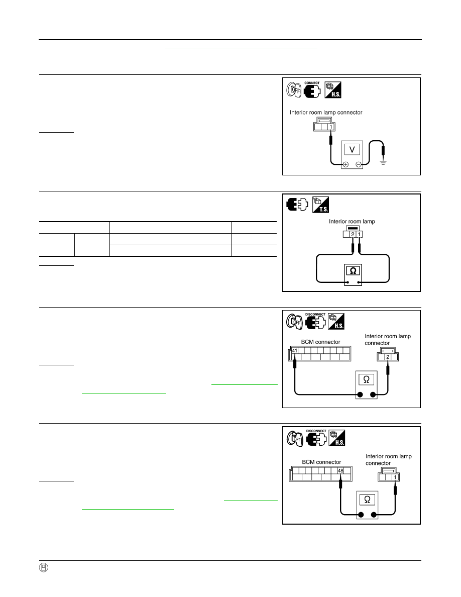
CHECK INTERIOR ROOM LAMP INPUT
1.
Turn ignition switch OFF.
2.
Check voltage between interior room lamp harness connector
R53 terminal 1 and ground.
OK or NG
OK
>> GO TO 6.
NG
>> GO TO 4.
4.
CHECK INTERIOR ROOM LAMP
1.
Disconnect interior room lamp connector.
2.
Check continuity between interior room lamp.
OK or NG
OK
>> GO TO 5.
NG
>> Replace Interior room lamp.
5.
CHECK INTERIOR ROOM LAMP CIRCUIT
1.
Disconnect BCM connector.
2.
Check continuity between BCM harness connector M4 terminal
41 and interior room lamp harness connector R53 terminal 2.
OK or NG
OK
>> Replace BCM if interior room lamp does not work after
setting the connector again. Refer to
NG
>> Repair harness or connector.
6.
CHECK INTERIOR ROOM LAMP CIRCUIT
1.
Disconnect BCM connector and interior room lamp connector.
2.
Check continuity between BCM harness connector M4 terminal
48 and interior room lamp harness connector R53 terminal 1.
OK or NG
OK
>> Replace BCM if interior room lamp does not work after
setting the connector again. Refer to
.
NG
>> Repair harness or connector.
Map Lamp Control Does Not Operate
INFOID:0000000001381757
1.
CHECK EACH SWITCH
CONSULT-III DATA MONITOR
1 – Ground
: Battery voltage.
PKIA5249E
Interior room lamp
Condition
Continuity
1
2
Interior room lamp switch is DOOR.
Yes
Interior room lamp switch is OFF or ON.
No
PKIB3509E
41 – 2
: Continuity should exist.
PKIB3511E
48 – 1
: Continuity should exist.
PKIB3510E
Нет комментариевНе стесняйтесь поделиться с нами вашим ценным мнением.
Текст