Infiniti FX35 / FX45. Manual — part 673

TIMING CHAIN
EM-209
< SERVICE INFORMATION >
[VK45DE]
C
D
E
F
G
H
I
J
K
L
M
A
EM
N
P
O
c.
Apply a continuous bead of liquid gasket with tube presser
(commercial service tool) to intake valve timing control covers as
shown in the figure.
Use Genuine RTV Silicone Sealant or equivalent. Refer to
GI-44, "Recommended Chemical Product and Sealant"
d.
Tighten mounting bolts in numerical order as shown in the fig-
ure.
12. Install intake valve timing control position sensor, intake valve timing control solenoid valve and camshaft
position sensor (PHASE) to intake valve timing control cover and front cover if removed.
• Be sure to tighten mounting bolts with flanges completely seated.
13. Install oil pan and oil strainer. Refer to
14. Install crankshaft pulley as follows:
a.
Fix crankshaft with ring gear stopper [SST: J-45476].
b.
Install crankshaft pulley, taking care not to damage front oil seal.
• Install according to dowel pin of oil pump drive spacer.
• Lightly tapping its center with plastic hammer, insert pulley.
CAUTION:
Do not tap pulley on the side surface where belt is installed (outer circumference).
c.
Apply engine oil onto threaded parts of crankshaft pulley bolt and seating area.
d.
Tighten crankshaft pulley bolt.
e.
Put a paint mark on crankshaft pulley aligning with angle mark on crankshaft pulley bolt.
f.
Further tighten by 90 degrees. (Angle tightening)
• Check the tightening angle by referencing to the notches. The
angle between two notches is 90 degrees.
15. Rotate crankshaft pulley in normal direction (clockwise when viewed from engine front) to confirm it turns
smoothly.
16. Install in the reverse order of removal after this step.
NOTE:
SBIA0375E
PBIC0051E
: 93.1 N·m (9.5 kg-m, 69 ft-lb)
PBIC2346E
EM-210
< SERVICE INFORMATION >
[VK45DE]
TIMING CHAIN
If hydraulic pressure inside timing chain tensioner drops after removal/installation, slack in guide may gen-
erate a pounding noise during and just after engine start. However, this does not indicate an unusualness.
Noise will stop after hydraulic pressure rises.
INSPECTION AFTER INSTALLATION
Inspection for Leaks
The followings are procedures for checking fluids leak, lubricates leak and exhaust gases leak.
• Before starting engine, check oil/fluid levels including engine coolant and engine oil. If less than required
quantity, fill to the specified level. Refer to
• Use procedure below to check for fuel leakage.
- Turn ignition switch “ON” (with engine stopped). With fuel pressure applied to fuel piping, check for fuel leak-
age at connection points.
- Start engine. With engine speed increased, check again for fuel leakage at connection points.
• Run engine to check for unusual noise and vibration.
• Warm up engine thoroughly to make sure there is no leakage of fuel, exhaust gases, or any oil/fluids includ-
ing engine oil and engine coolant.
• Bleed air from lines and hoses of applicable lines, such as in cooling system.
• After cooling down engine, again check oil/fluid levels including engine oil and engine coolant. Refill to the
specified level, if necessary.
Summary of the inspection items:
*: Transmission/transaxle/CVT fluid. power steering fluid, brake fluid, etc.
Items
Before starting engine
Engine running
After engine stopped
Engine coolant
Level
Leakage
Level
Engine oil
Level
Leakage
Level
Other oils and fluid*
Level
Leakage
Level
Fuel
Leakage
Leakage
Leakage
Exhaust gases
—
Leakage
—
CAMSHAFT
EM-211
< SERVICE INFORMATION >
[VK45DE]
C
D
E
F
G
H
I
J
K
L
M
A
EM
N
P
O
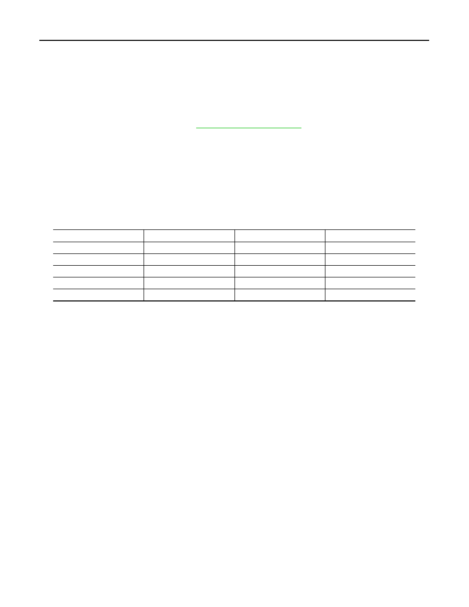
CAMSHAFT
Component
INFOID:0000000001325790
• Refer to
Removal and Installation
INFOID:0000000001325791
REMOVAL
1.
Remove engine assembly from vehicle. Refer to
2.
Remove timing chain. Refer to
1.
Cylinder head (right bank)
2.
Camshaft bracket (No. 2 to 5)
3.
Valve lifter
4.
Camshaft bracket (No. 1)
5.
Washer
6.
Camshaft (EXH)
7.
Camshaft sprocket (EXH)
8.
Camshaft sprocket (INT)
9.
Camshaft (INT)
10.
Bracket
11.
Cylinder head (left bank)
12.
Valve lifter
13.
Camshaft (INT)
14.
Camshaft sprocket (INT)
15.
Camshaft sprocket (EXH)
16.
Camshaft (EXH)
17.
Camshaft bracket (No. 1)
18.
Washer
19.
Camshaft bracket (No. 2 to 5)
20.
Camshaft bracket (No. 6)
A.
PBIC5276E
EM-212
< SERVICE INFORMATION >
[VK45DE]
CAMSHAFT
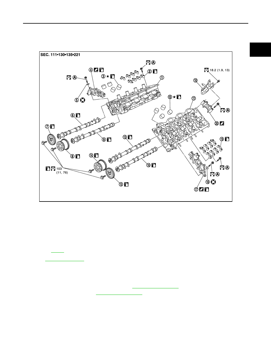
3.
With hexagonal part of camshaft locked with wrench, loosen
bolts securing camshaft sprocket to remove camshaft sprocket.
CAUTION:
• Do not loosen mounting bolts with securing anything
other than the camshaft hexagonal portion or with ten-
sioning the timing chain.
• After removing timing chain, do not turn crankshaft and
camshaft separately, or valves will strike the piston head.
4.
Remove intake and exhaust camshaft brackets.
• Mark camshafts, camshaft brackets and bolts so placed in the same position and direction for installa-
tion.
• Equally loosen camshaft brackets and bolts in several steps in
reverse order as shown in the figure.
• Lightly tapping with plastic hammer, remove camshaft bracket
(No. 1) and camshaft bracket (No. 6).
NOTE:
The bottom surface of each bracket will be stuck to cylinder
head because of liquid gasket.
5.
Remove camshaft.
6.
Remove valve lifter if necessary.
• Identify installation positions, and store them without mixing them up.
INSPECTION AFTER REMOVAL
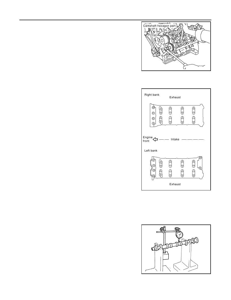
Camshaft Runout
1.
Put V-block on precise flat table, and support No. 2 and 5 journal
of camshaft.
CAUTION:
Do not support journal No. 1 (on the side of camshaft
sprocket) because it has a different diameter from the other
four locations.
2.
Set dial indicator vertically to No. 3 journal.
3.
Turn camshaft to one direction with hands, and measure the
camshaft runout on dial indicator. (Total indicator reading)
4.
If it exceeds the limit, replace camshaft.
Camshaft Cam Height
PBIC0030E
PBIC0031E
Limit
: 0.02 mm (0.001 in)
PBIC2499E
Нет комментариевНе стесняйтесь поделиться с нами вашим ценным мнением.
Текст