Infiniti FX35 / FX45. Manual — part 672
TIMING CHAIN
EM-205
< SERVICE INFORMATION >
[VK45DE]
C
D
E
F
G
H
I
J
K
L
M
A
EM
N
P
O
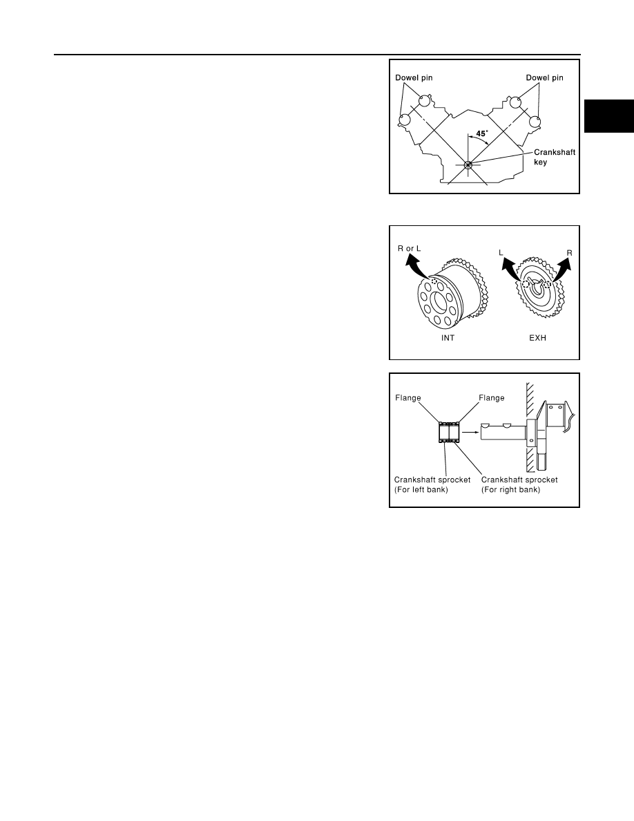
1.
Make sure that crankshaft key and dowel pin of each camshaft
are located as shown in the figure. (No. 1 cylinder at compres-
sion TDC)
NOTE:
Though camshaft does not stop at the position as shown in the
figure, for the placement of cam nose, it is generally accepted
camshaft is placed for the same direction of the figure.
2.
Install camshaft sprockets.
• Install onto correct side by checking with identification mark on
surface.
• Install camshaft sprocket (EXH) by selectively using the
groove of dowel pin according to the bank. (Common part
used for both banks.)
• Lock the hexagonal part of camshaft in the same procedure as
for removal, and tighten mounting bolts.
3.
Install crankshaft sprockets for both banks.
• Install each crankshaft sprocket so that its flange side (the
larger diameter side without teeth) faces in the direction shown
in the figure.
NOTE:
The same parts are used but facing directions are different.
Camshaft dowel pin
: At cylinder head upper face side in each bank
Crankshaft key
: At cylinder head side of left bank
SBIA0356E
PBIC2345E
PBIC0057E
EM-206
< SERVICE INFORMATION >
[VK45DE]
TIMING CHAIN
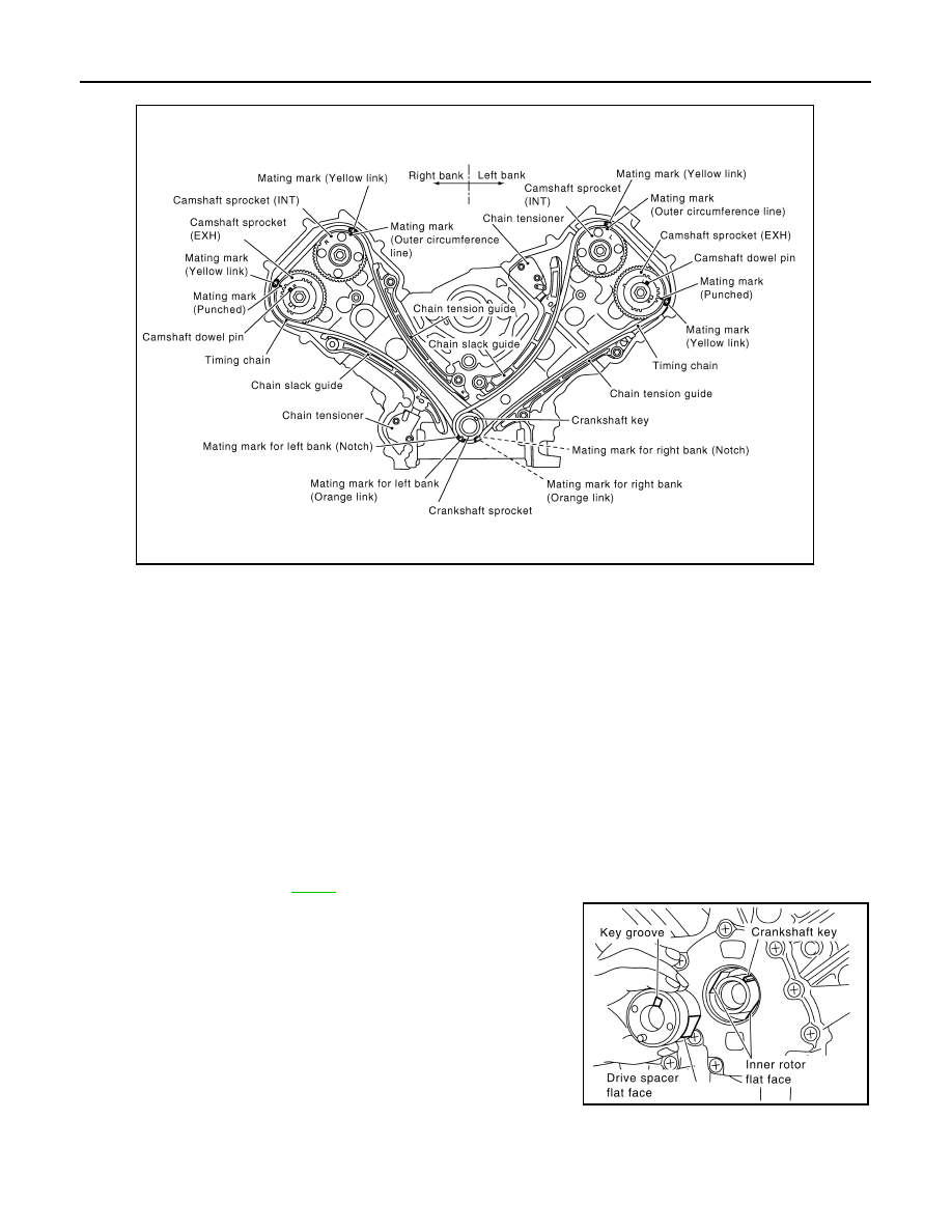
4.
Install timing chains and related parts.
• Align the mating mark on each sprocket and timing chain for installation.
NOTE:
Before installing chain tensioner, it is possible to change the position of mating mark on timing chain for
that on each sprocket for alignment.
CAUTION:
For the above reason, after the mating marks are aligned, keep them aligned by holding them
with a hand.
• Install slack guides and tension guides onto correct side by checking with identification mark on surface.
• Install chain tensioner with plunger fixed as described in its removal.
CAUTION:
• Before and after the installation of chain tensioner, make sure that the mating mark on timing
chain is not out of alignment.
• After installing chain tensioner, remove stopper pin to release tensioner. Make sure tensioner
is released.
• To avoid chain-link skipping of timing chain, do not move crankshaft or camshafts until front
cover is installed.
5.
Perform the same procedure as for right bank, install timing chain and related parts on left side.
6.
Install oil pump. Refer to
.
7.
Install oil pump drive spacer as follows:
a.
Insert oil pump drive spacer according to the directions of crank-
shaft key and the two flat surfaces of oil pump inner rotor.
• If the positional relationship does not allow the insertion, rotate
oil pump inner rotor with a finger to allow spacer.
b.
After confirming that the position of each part is in correct condi-
tion to allow for spacer, force fit spacer by lightly tapping with
plastic hammer until it contacts and does not go further.
8.
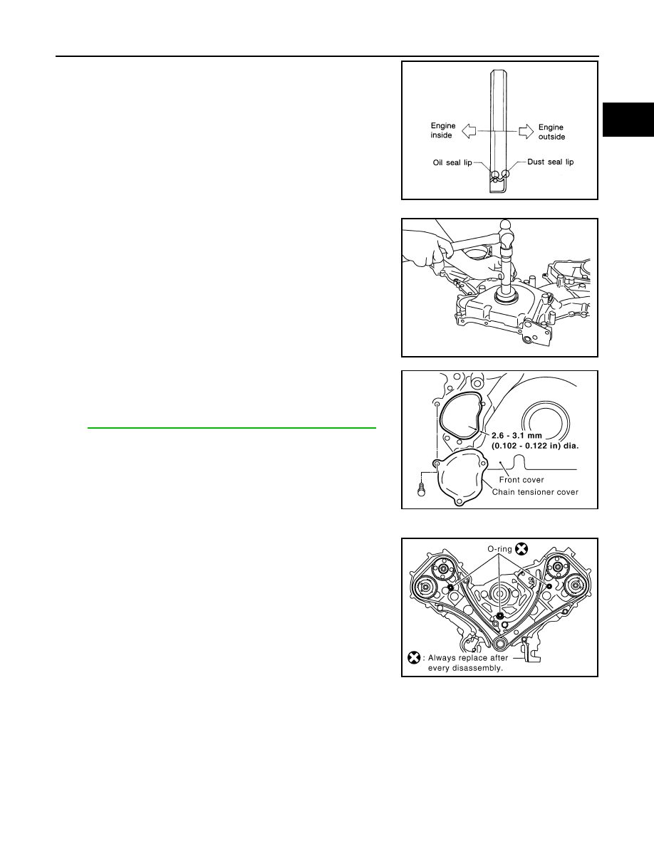
Install front oil seal on front cover.
• Apply new engine oil to both oil seal lip and dust seal lip.
PBIC2344E
PBIC0058E
TIMING CHAIN
EM-207
< SERVICE INFORMATION >
[VK45DE]
C
D
E
F
G
H
I
J
K
L
M
A
EM
N
P
O
• Install it so that each seal lip is oriented as shown in the figure.
CAUTION:
Be careful not to scratch or make burrs on circumference
of oil seal.
• Using front oil seal drift (commercial service tool), press fit until
the height of front oil seal is level with the mounting surface.
• Make sure the garter spring is in position and seal lips not
inverted.
9.
Install chain tensioner cover to front cover.
• Apply a continuous bead of liquid gasket with tube presser
(commercial service tool) to front cover as shown in the figure.
Use Genuine RTV Silicone Sealant or equivalent. Refer to
GI-44, "Recommended Chemical Product and Sealant"
.
10. Install front cover as follows:
a.
Install new O-rings onto cylinder heads (right and left bank) and
cylinder block.
SEM715A
Front oil seal drift
Outer diameter
: 56 mm (2.20 in)
Inner diameter
: 49 mm (1.93 in)
PBIC0059E
SBIA0372E
SBIA0373E
EM-208
< SERVICE INFORMATION >
[VK45DE]
TIMING CHAIN
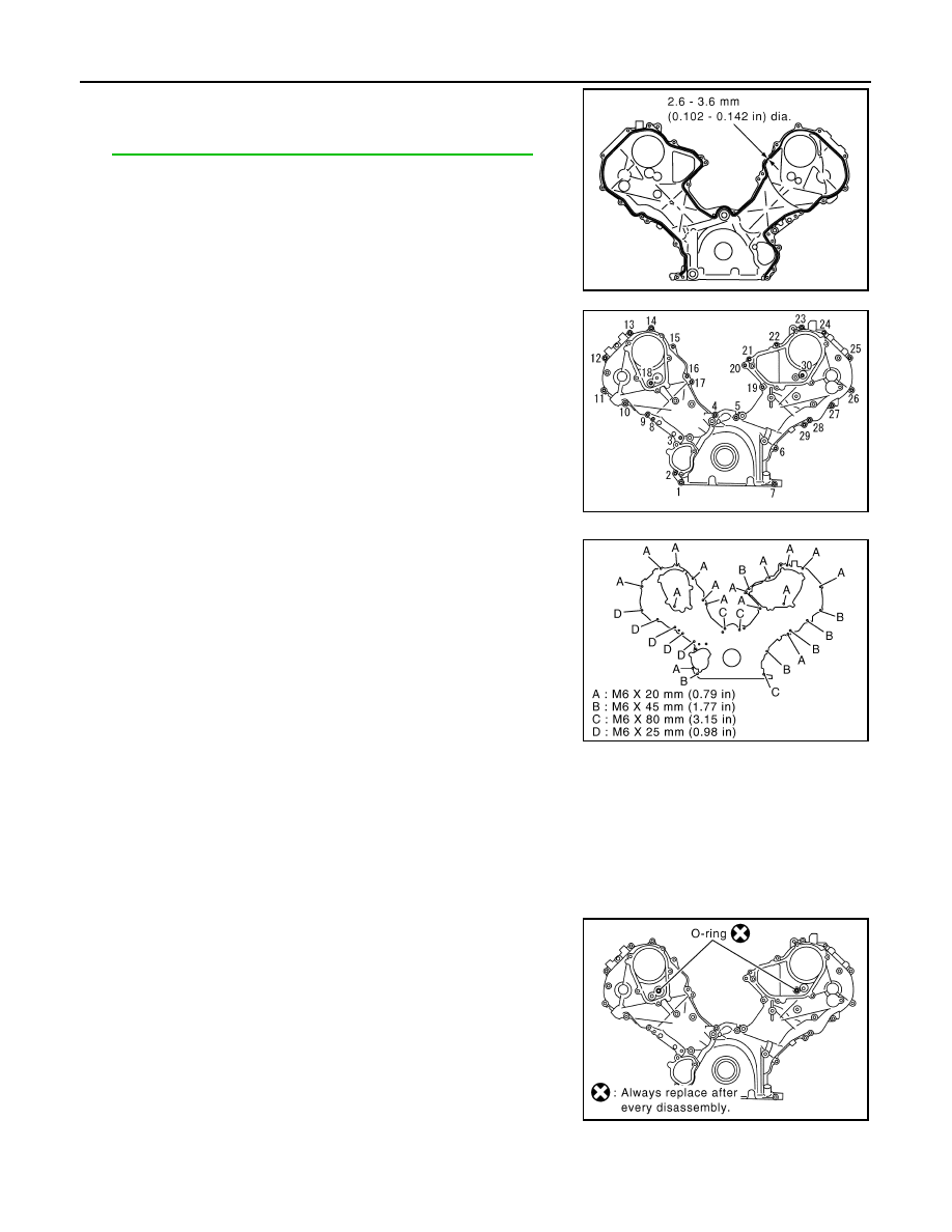
b.
Apply a continuous bead of liquid gasket with tube presser
(commercial service tool) to front cover as shown in the figure.
Use Genuine RTV Silicone Sealant or equivalent. Refer to
GI-44, "Recommended Chemical Product and Sealant"
c.
make sure again that the mating marks on timing chain and that
on each sprocket are aligned. Then, install front cover.
CAUTION:
Be careful to avoid interference with the front end of oil
pump drive spacer. Such interference may damage front oil
seal.
d.
Tighten mounting bolts in numerical order as shown in the fig-
ure.
• There are four type mounting bolts.
e.
After all mounting bolts are tightened, retighten them in numerical order as shown in the figure.
CAUTION:
Be sure to wipe off any excessive liquid gasket leaking onto surface mating with oil pan.
11. Install intake valve timing control cover as follows:
a.
At the back of intake valve timing control cover, install new seal rings (three for each bank) to the area to
be inserted into camshaft sprocket (INT).
CAUTION:
Do not spread seal ring excessively to avoid breaks and deformation.
b.
Install new O-rings on front cover.
PBIC0062E
KBIA0354J
PBIC1681E
SBIA0374E
Нет комментариевНе стесняйтесь поделиться с нами вашим ценным мнением.
Текст