Infiniti FX35 / FX45. Manual — part 511

DTC P0130, P0150 A/F SENSOR 1
EC-805
< SERVICE INFORMATION >
[VK45DE]
C
D
E
F
G
H
I
J
K
L
M
A
EC
N
P
O
NG
>> Repair open circuit or short to ground or short to power in harness or connectors.
5.
CHECK INTERMITTENT INCIDENT
Perform
OK or NG
OK
>> GO TO 6.
NG
>> Repair or replace.
6.
REPLACE AIR FUEL RATIO (A/F) SENSOR 1
Replace malfunctioning air fuel ratio (A/F) sensor 1.
CAUTION:
• Discard any A/F sensor which has been dropped from a height of more than 0.5 m (19.7 in) onto a
hard surface such as a concrete floor; use a new one.
• Before installing new A/F sensor, clean exhaust system threads using Oxygen Sensor Thread
Cleaner tool J-43897-18 or J-43897-12 and approved anti-seize lubricant.
>> INSPECTION END
Removal and Installation
INFOID:0000000001326649
AIR FUEL RATIO (A/F) SENSOR 1
.
EC-806
< SERVICE INFORMATION >
[VK45DE]
DTC P0131, P0151 A/F SENSOR 1
DTC P0131, P0151 A/F SENSOR 1
Component Description
INFOID:0000000001326650
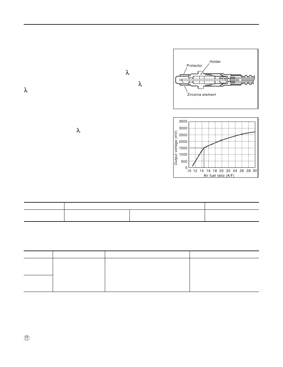
The air fuel ratio (A/F) sensor 1 is a planar dual-cell limit current sen-
sor. The sensor element of the A/F sensor 1 is the combination of a
Nernst concentration cell (sensor cell) with an oxygen-pump cell,
which transports ions. It has a heater in the element.
The sensor is capable of precise measurement = 1, but also in the
lean and rich range. Together with its control electronics, the sensor
outputs a clear, continuous signal throughout a wide range (0.7 <
< air).
The exhaust gas components diffuse through the diffusion gap at the
electrode of the oxygen pump and Nernst concentration cell, where
they are brought to thermodynamic balance.
An electronic circuit controls the pump current through the oxygen-
pump cell so that the composition of the exhaust gas in the diffusion
gap remains constant at = 1. Therefore, the A/F sensor 1 is able to
indicate air/fuel ratio by this pumping of current. In addition, a heater
is integrated in the sensor to ensure the required operating tempera-
ture of 700 - 800
°
C (1,292 - 1,472
°
F).
CONSULT-III Reference Value in Data Monitor Mode
INFOID:0000000001326651
Specification data are reference values.
On Board Diagnosis Logic
INFOID:0000000001326652
To judge the malfunction, the diagnosis checks that the A/F signal computed by ECM from the A/F sensor 1
signal is not inordinately low.
DTC Confirmation Procedure
INFOID:0000000001326653
NOTE:
If DTC Confirmation Procedure has been previously conducted, always turn ignition switch OFF and wait at
least 10 seconds before conducting the next test.
TESTING CONDITION:
Before performing the following procedure, confirm that battery voltage is more than 10.5V at idle.
WITH CONSULT-III
1.
Start engine and warm it up to normal operating temperature.
SEF579Z
SEF580Z
MONITOR ITEM
CONDITION
SPECIFICATION
A/F SEN1 (B1)
A/F SEN1 (B2)
• Engine: After warming up
Maintaining engine speed at 2,000 rpm
Fluctuates around 1.5 V
DTC No.
Trouble diagnosis name
DTC detecting condition
Possible Cause
P0131
0131
(Bank 1)
Air fuel ratio (A/F) sensor 1
circuit low voltage
The A/F signal computed by ECM from the A/F
sensor 1 signal is constantly approx. 0V.
• Harness or connectors
(The A/F sensor 1 circuit is open or
shorted.)
• A/F sensor 1
P0151
0151
(Bank 2)

DTC P0131, P0151 A/F SENSOR 1
EC-807
< SERVICE INFORMATION >
[VK45DE]
C
D
E
F
G
H
I
J
K
L
M
A
EC
N
P
O
2.
Select “A/F SEN1 (B1)” or “A/F SEN1 (B2)” in “DATA MONITOR” mode with CONSULT-III.
3.
Check “A/F SEN1 (B1)” or “A/F SEN1 (B2)” indication.
If the indication is constantly approx. 0V, go to
If the indication is not constantly approx. 0V, go to next step.
4.
Turn ignition switch OFF, wait at least 10 seconds and then restart engine.
5.
Drive and accelerate vehicle to more than 40 km/h (25 MPH) within 20 seconds after restarting engine.
6.
Maintain the following conditions for about 20 consecutive seconds.
NOTE:
• Keep the accelerator pedal as steady as possible during the cruising.
• If this procedure is not completed within 1 minute after restarting engine at step 4, return to step
4.
7.
Check 1st trip DTC.
8.
If 1st trip DTC is displayed, go to
WITH GST
Follow the procedure “WITH CONSULT-III” above.
ENG SPEED
1,000 - 3,200 rpm
VHCL SPEED SE
More than 40 km/h (25 MPH)
B/FUEL SCHDL
1.5 - 9.0 msec
Gear position
Suitable position
EC-808
< SERVICE INFORMATION >
[VK45DE]
DTC P0131, P0151 A/F SENSOR 1
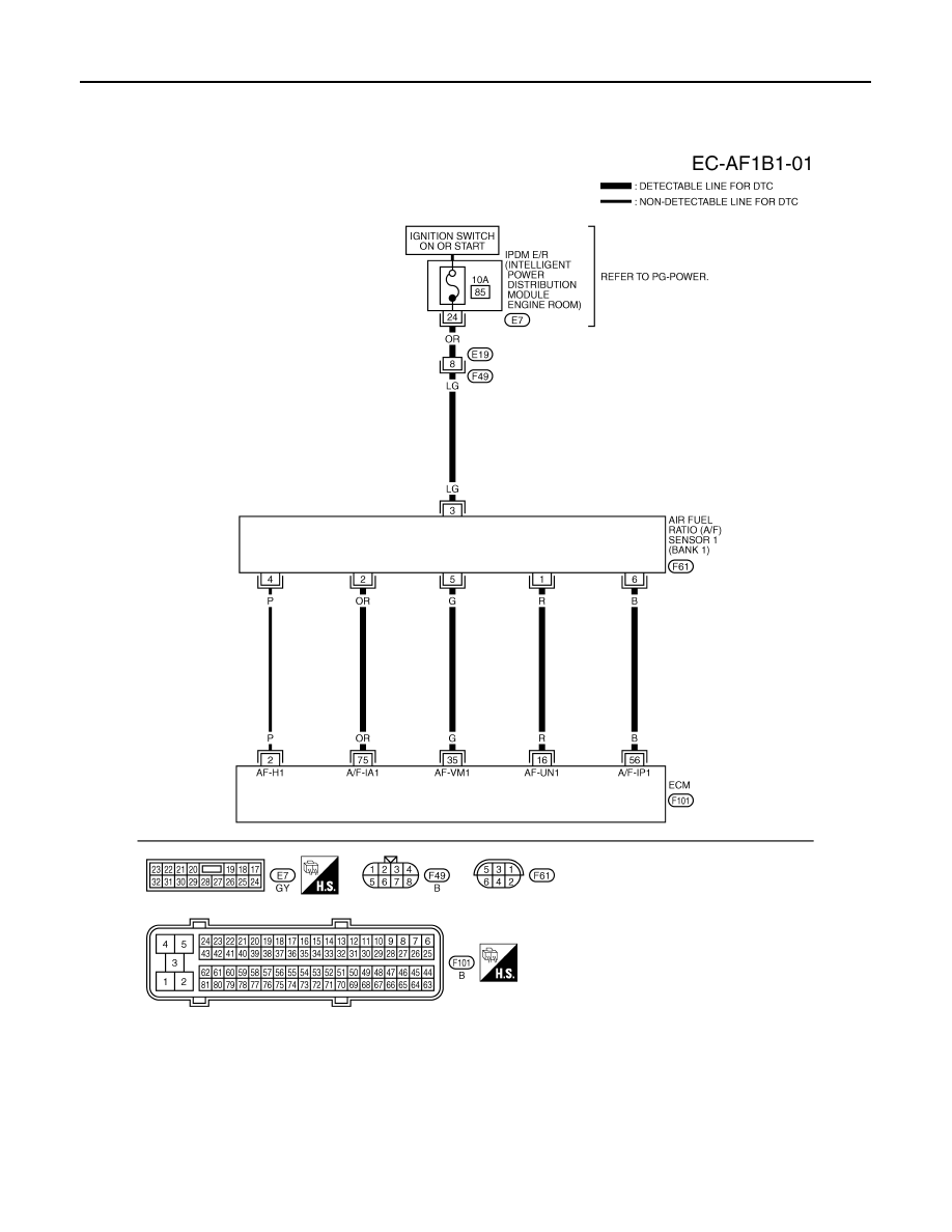
Wiring Diagram
INFOID:0000000001326654
BANK 1
Specification data are reference values and are measured between each terminal and ground.
Pulse signal is measured by CONSULT-III.
CAUTION:
TBWM1373E
Нет комментариевНе стесняйтесь поделиться с нами вашим ценным мнением.
Текст