Infiniti FX35 / FX45. Manual — part 509
DTC P0128 THERMOSTAT FUNCTION
EC-797
< SERVICE INFORMATION >
[VK45DE]
C
D
E
F
G
H
I
J
K
L
M
A
EC
N
P
O
Component Inspection
INFOID:0000000001326640
ENGINE COOLANT TEMPERATURE SENSOR
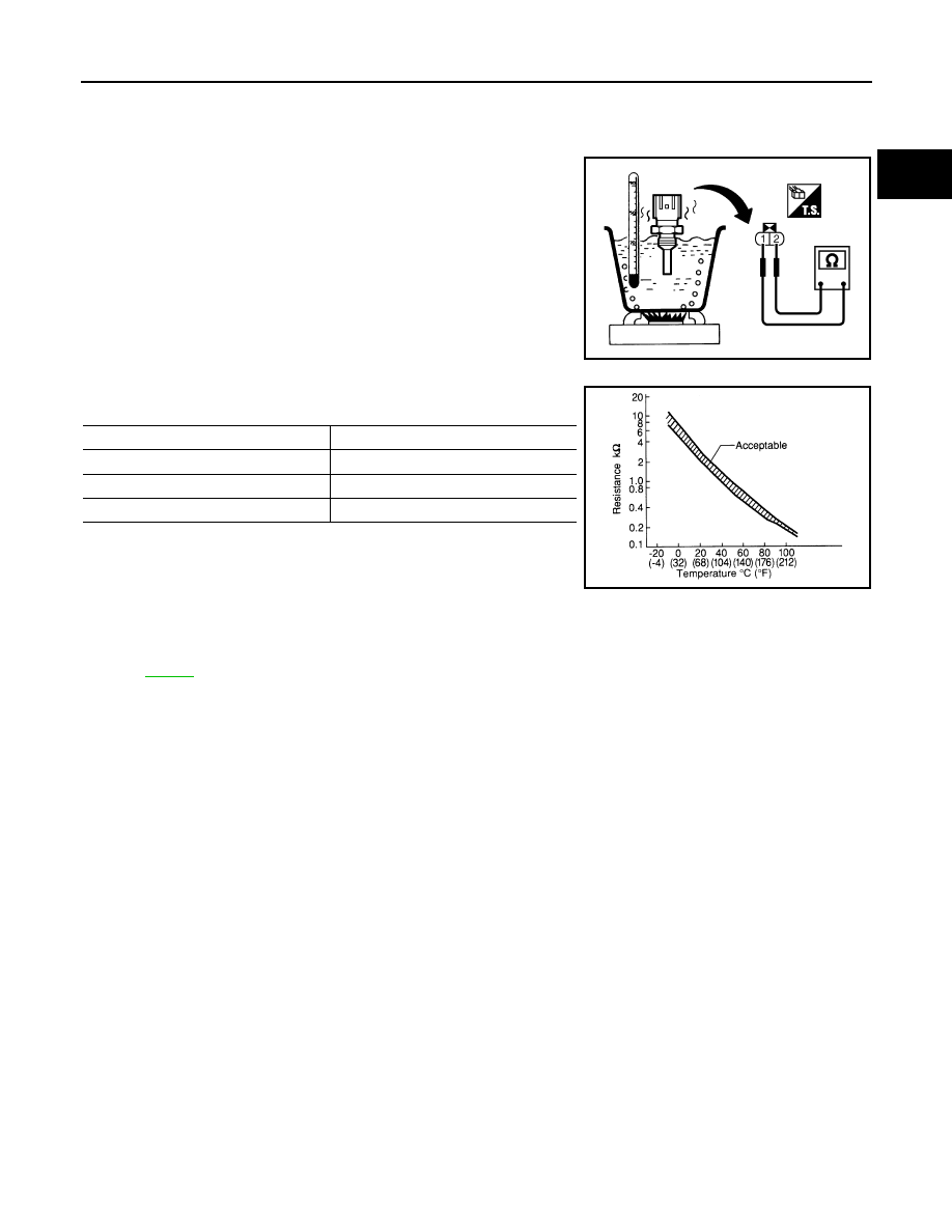
1.
Check resistance between engine coolant temperature sensor
terminals 1 and 2 as shown in the figure.
<Reference data>
2.
If NG, replace engine coolant temperature sensor.
Removal and Installation
INFOID:0000000001326641
ENGINE COOLANT TEMPERATURE SENSOR
PBIB2005E
Temperature
°
C (
°
F)
Resistance k
Ω
20 (68)
2.1 - 2.9
50 (122)
0.68 - 1.0
90 (194)
0.236 - 0.260
SEF012P
EC-798
< SERVICE INFORMATION >
[VK45DE]
DTC P0130, P0150 A/F SENSOR 1
DTC P0130, P0150 A/F SENSOR 1
Component Description
INFOID:0000000001326642
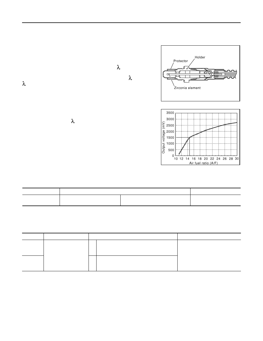
The air fuel ratio (A/F) sensor 1 is a planar dual-cell limit current sen-
sor. The sensor element of the A/F sensor 1 is the combination of a
Nernst concentration cell (sensor cell) with an oxygen-pump cell,
which transports ions. It has a heater in the element.
The sensor is capable of precise measurement = 1, but also in the
lean and rich range. Together with its control electronics, the sensor
outputs a clear, continuous signal throughout a wide range (0.7 <
< air).
The exhaust gas components diffuse through the diffusion gap at the
electrode of the oxygen pump and Nernst concentration cell, where
they are brought to thermodynamic balance.
An electronic circuit controls the pump current through the oxygen-
pump cell so that the composition of the exhaust gas in the diffusion
gap remains constant at = 1. Therefore, the A/F sensor 1 is able to
indicate air/fuel ratio by this pumping of current. In addition, a heater
is integrated in the sensor to ensure the required operating tempera-
ture of 700 - 800
°
C (1,292 - 1,472
°
F).
CONSULT-III Reference Value in Data Monitor Mode
INFOID:0000000001326643
Specification data are reference values.
On Board Diagnosis Logic
INFOID:0000000001326644
To judge the malfunction, the diagnosis checks that the A/F signal computed by ECM from the A/F sensor 1
signal fluctuates according to fuel feedback control.
DTC Confirmation Procedure
INFOID:0000000001326645
Perform PROCEDURE FOR MALFUNCTION A first.
If the DTC cannot be confirmed, perform PROCEDURE FOR MALFUNCTION B.
NOTE:
If DTC Confirmation Procedure has been previously conducted, always turn ignition switch OFF and wait at
least 10 seconds before conducting the next test.
TESTING CONDITION:
Before performing the following procedure, confirm that battery voltage is more than 11V at idle.
PROCEDURE FOR MALFUNCTION A
SEF579Z
SEF580Z
MONITOR ITEM
CONDITION
SPECIFICATION
A/F SEN1 (B1)
A/F SEN1 (B2)
• Engine: After warming up
Maintaining engine speed at 2,000 rpm
Fluctuates around 1.5 V
DTC No.
Trouble diagnosis name
DTC detecting condition
Possible Cause
P0130
0130
(Bank 1)
Air fuel ratio (A/F) sensor
1 circuit
A)
The A/F signal computed by ECM from the A/F
sensor 1 signal is constantly in the range other
than approx. 1.5V.
• Harness or connectors
[Air fuel ratio (A/F) sensor 1 circuit
is open or shorted.]
• Air fuel ratio (A/F) sensor 1
P0150
0150
(Bank 2)
B)
The A/F signal computed by ECM from the A/F
sensor 1 signal is constantly approx. 1.5V.

DTC P0130, P0150 A/F SENSOR 1
EC-799
< SERVICE INFORMATION >
[VK45DE]
C
D
E
F
G
H
I
J
K
L
M
A
EC
N
P
O
1.
Start engine and warm it up to normal operating temperature.
2.
Let engine idle for 2 minutes.
3.
Check 1st trip DTC.
4.
If 1st trip DTC is detected, go to
PROCEDURE FOR MALFUNCTION B
CAUTION:
Always drive vehicle at a safe speed.
With CONSULT-III
1.
Start engine and warm it up to normal operating temperature.
2.
Select “A/F SEN1 (B1)” or “A/F SEN1 (B2)” in “DATA MONITOR” mode with CONSULT-III.
3.
Check “A/F SEN1 (B1)” or “A/F SEN1 (B2)” indication.
If the indication is constantly approx. 1.5V and does not fluctuates, go to
.
If the indication fluctuates around 1.5V, go to next step.
4.
Select “A/F SEN1 (B1) P1276” (for DTC P0130) or “A/F SEN1 (B2) P1286” (for DTC P0150) of “A/F
SEN1” in “DTC WORK SUPPORT” mode with CONSULT-III.
5.
Touch “START”.
6.
When the following conditions are met, “TESTING” will be displayed on the CONSULT-III screen.
If “TESTING” is not displayed after 20 seconds, retry from step 2.
7.
Release accelerator pedal fully.
NOTE:
Never apply brake during releasing the accelerator pedal.
8.
Make sure that “TESTING” changes to “COMPLETED”.
If “TESTING” changed to “OUT OF CONDITION”, retry from step 6.
9.
Make sure that “OK” is displayed after touching “SELF-DIAG RESULT”.
If “NG” is displayed, go to
.
Overall Function Check
INFOID:0000000001326646
PROCEDURE FOR MALFUNCTION B
Use this procedure to check the overall function of the A/F sensor 1 circuit. During this check, a 1st trip DTC
might not be confirmed.
With GST
1.
Start engine and warm it up to normal operating temperature.
2.
Drive the vehicle at a speed of 80 km/h (50 MPH) for a few minutes in the suitable gear position.
3.
Set D position, then release the accelerator pedal fully until the vehicle speed decreases to 50 km/h (30
MPH).
NOTE:
Never apply brake during releasing the accelerator pedal.
4.
Repeat steps 2 to 3 for five times.
5.
Stop the vehicle and turn ignition switch OFF.
6.
Wait at least 10 seconds and restart engine.
7.
Repeat steps 2 to 3 for five times.
8.
Stop the vehicle and connect GST to the vehicle.
9.
Make sure that no DTC is displayed.
If the DTC is displayed, go to
ENG SPEED
1,300 - 3,200 rpm
VHCL SPEED SE
More than 64 km/h (40 MPH)
B/FUEL SCHDL
1.0 - 8.0 msec
Selector lever
D position
EC-800
< SERVICE INFORMATION >
[VK45DE]
DTC P0130, P0150 A/F SENSOR 1
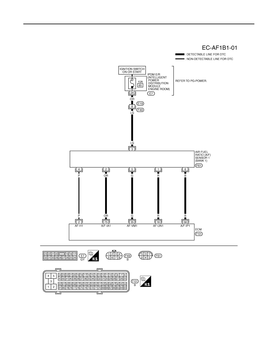
Wiring Diagram
INFOID:0000000001326647
BANK 1
Specification data are reference values and are measured between each terminal and ground.
Pulse signal is measured by CONSULT-III.
CAUTION:
TBWM1373E
Нет комментариевНе стесняйтесь поделиться с нами вашим ценным мнением.
Текст