Infiniti FX35 / FX45. Manual — part 268
CO-2
RADIATOR (ALUMINUM TYPE) . . . . . ...
Component . . . . . . . . . . . . . . . .
Disassembly and Assembly . . . . . . . . ....
COOLING FAN . . . . . . . . . . . . ..
Component (Crankshaft Driven type) . . . . . .
Removal and Installation . . . . . . . . . ....
Component (Motor Driven Type) . . . . . . ....
Removal and Installation . . . . . . . . . ....
Disassembly and Assembly (Motor Driven Type) ...
WATER PUMP . . . . . . . . . . . . ...
Component . . . . . . . . . . . . . . . .
Removal and Installation . . . . . . . . . . .
THERMOSTAT AND WATER CONTROL
VALVE . . . . . . . . . . . . . . . ...
Component . . . . . . . . . . . . . . . .
Removal and Installation . . . . . . . . . . .
SERVICE DATA AND SPECIFICATIONS
(SDS) . . . . . . . . . . . . . . . . .
PRECAUTIONS
CO-3
< SERVICE INFORMATION >
[VQ35DE]
C
D
E
F
G
H
I
J
K
L
M
A
CO
N
P
O
SERVICE INFORMATION
PRECAUTIONS
Precaution for Supplemental Restraint System (SRS) "AIR BAG" and "SEAT BELT
PRE-TENSIONER"
INFOID:0000000001612910
The Supplemental Restraint System such as “AIR BAG” and “SEAT BELT PRE-TENSIONER”, used along
with a front seat belt, helps to reduce the risk or severity of injury to the driver and front passenger for certain
types of collision. This system includes seat belt switch inputs and dual stage front air bag modules. The SRS
system uses the seat belt switches to determine the front air bag deployment, and may only deploy one front
air bag, depending on the severity of a collision and whether the front occupants are belted or unbelted.
Information necessary to service the system safely is included in the “SUPPLEMENTAL RESTRAINT SYS-
TEM” and “SEAT BELTS” of this Service Manual.
WARNING:
• To avoid rendering the SRS inoperative, which could increase the risk of personal injury or death in
the event of a collision which would result in air bag inflation, all maintenance must be performed by
an authorized NISSAN/INFINITI dealer.
• Improper maintenance, including incorrect removal and installation of the SRS, can lead to personal
injury caused by unintentional activation of the system. For removal of Spiral Cable and Air Bag
Module, see the “SUPPLEMENTAL RESTRAINT SYSTEM”.
• Do not use electrical test equipment on any circuit related to the SRS unless instructed to in this
Service Manual. SRS wiring harnesses can be identified by yellow and/or orange harnesses or har-
ness connectors.
Precaution for Liquid Gasket
INFOID:0000000001325839
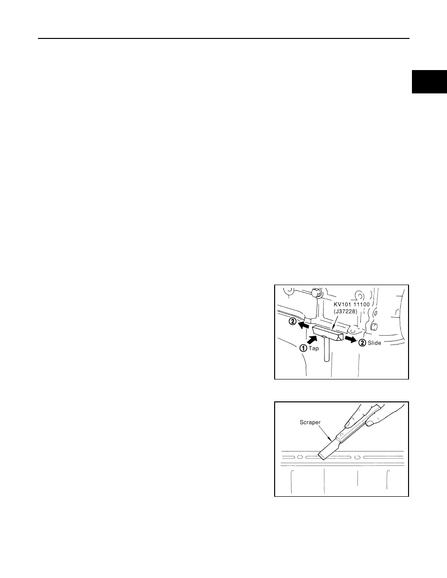
REMOVAL OF LIQUID GASKET SEALING
• After removing mounting nuts and bolts, separate the mating sur-
face using the seal cutter (SST) and remove old liquid gasket seal-
ing.
CAUTION:
Be careful not to damage the mating surfaces.
• Tap the seal cutter to insert it, and then slide it by tapping on the
side as shown in the figure.
• In areas where seal cutter is difficult to use, use a plastic hammer
to lightly tap the parts, to remove it.
CAUTION:
If for some unavoidable reason tool such as a screwdriver is
used, be careful not to damage the mating surfaces.
LIQUID GASKET APPLICATION PROCEDURE
1.
Using a scraper, remove old liquid gasket adhering to the liquid
gasket application surface and the mating surface.
• Remove liquid gasket completely from the groove of the liquid
gasket application surface, mounting bolts, and bolt holes.
2.
Wipe the liquid gasket application surface and the mating sur-
face with white gasoline (lighting and heating use) to remove
adhering moisture, grease and foreign materials.
PBIC0002E
PBIC0003E
CO-4
< SERVICE INFORMATION >
[VQ35DE]
PRECAUTIONS
3.
Attach liquid gasket tube to the tube presser (commercial ser-
vice tool).
Use Genuine RTV Silicone Sealant or equivalent. Refer to
GI-44, "Recommended Chemical Product and Sealant"
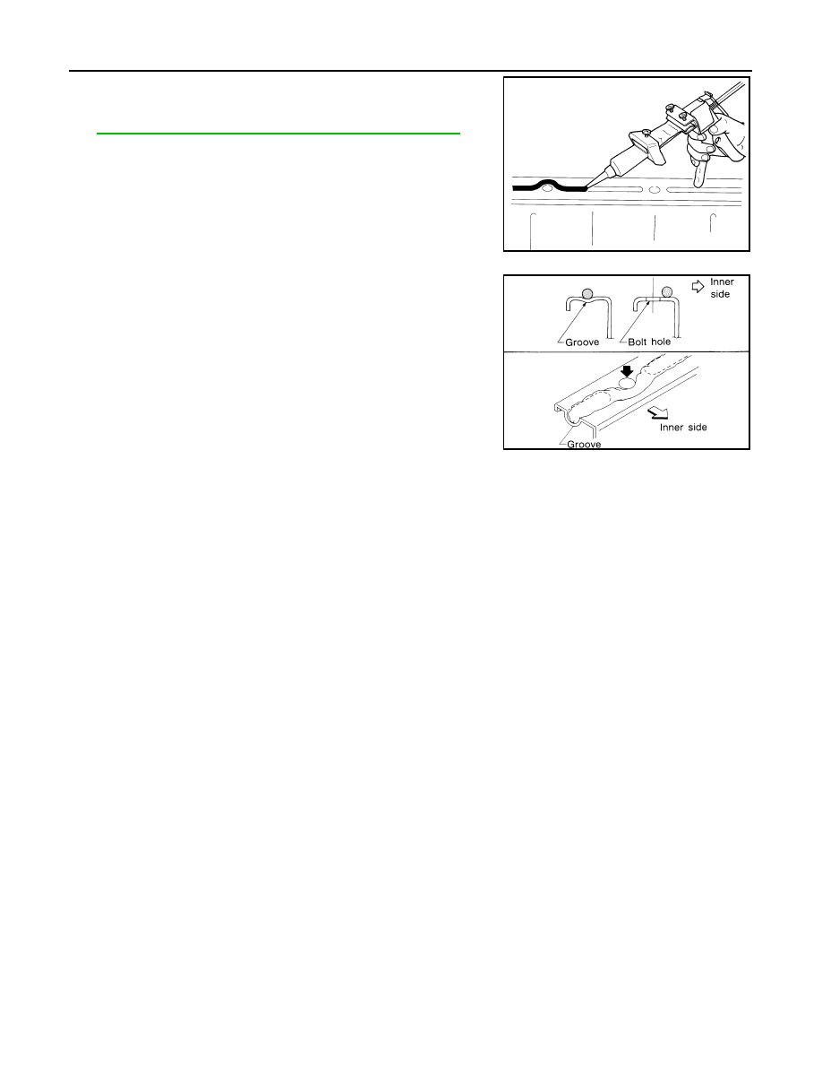
4.
Apply liquid gasket without breaks to the specified location with
the specified dimensions.
• If there is a groove for the liquid gasket application, apply liq-
uid gasket to the groove.
• As for the bolt holes, normally apply liquid gasket inside the
holes. Occasionally, it should be applied outside the holes.
Make sure to read the text of service manual.
• Within five minutes of liquid gasket application, install the mat-
ing component.
• If liquid gasket protrudes, wipe it off immediately.
• Do not retighten after mounting bolts and nuts the installation.
• After 30 minutes or more have passed from the installation, fill
engine oil and engine coolant.
CAUTION:
If there are specific instructions in this manual, observe them.
EMA0622D
SEM159F

PREPARATION
CO-5
< SERVICE INFORMATION >
[VQ35DE]
C
D
E
F
G
H
I
J
K
L
M
A
CO
N
P
O
PREPARATION
Special Service Tool
INFOID:0000000001325840
The actual shapes of Kent-Moore tools may differ from those of special service tools illustrated here.
Commercial Service Tool
INFOID:0000000001325841
Tool number
(Kent-Moore No.)
Tool name
Description
KV99103510
(
—
)
Radiator plate pliers A
Installing radiator upper and lower tanks
KV99103520
(
—
)
Radiator plate pliers B
Removing radiator upper and lower tanks
KV10111100
(J37228)
Seal cutter
Removing chain tensioner cover and water
pump cover
S-NT224
S-NT225
NT046
Tool name
Description
Tube presser
(
—
)
Pressing the tube of liquid gasket
Power tool
Loosening nuts and bolts
S-NT052
PBIC0190E
Нет комментариевНе стесняйтесь поделиться с нами вашим ценным мнением.
Текст