Infiniti FX35 / FX45. Manual — part 267
BRC-54
< SERVICE INFORMATION >
[VDC/TCS/ABS]
ACTUATOR AND ELECTRIC UNIT (ASSEMBLY)
ACTUATOR AND ELECTRIC UNIT (ASSEMBLY)
Removal and Installation
INFOID:0000000001327700
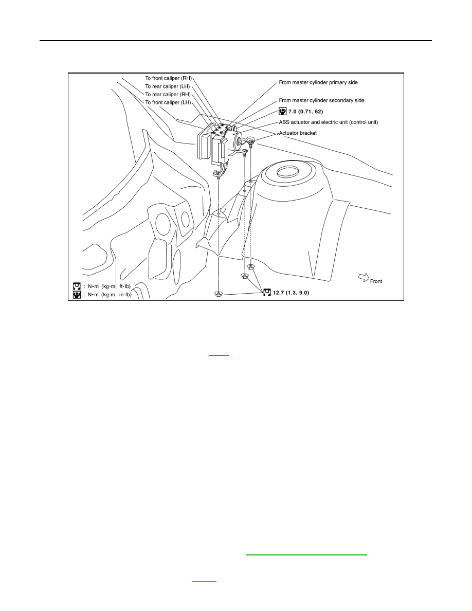
REMOVAL
1.
Disconnect ABS actuator and electric unit (control unit) connector.
2.
Loosen brake tube flare nuts, then remove brake tubes from ABS actuator and electric unit (control unit).
3.
Remove LH side fender protector. Refer to
4.
Remove ABS actuator and electric unit (control unit) mounting nuts.
5.
Remove ABS actuator and electric unit (control unit) from vehicle.
CAUTION:
Be careful of the following when removing ABS actuator and electric unit (control unit).
• If the part number on the part number label (pasted on actuator upper surface) is the same, ABS
actuator and electric unit (control unit) can not be used on another vehicle.
If it is used on another vehicle, ABS warning lamp, SLIP indicator lamp and VDC OFF indicator lamp
may turn ON or VDC/TCS/ABS may not operate normally.
When replacing ABS actuator and electric unit (control unit), must use new service parts.
• Before servicing, disconnect battery cables.
• To remove brake tube, use a flare nut torque wrench to prevent flare nuts and brake tube from being
damaged. To install, use a flare nut torque wrench (commercial service tool) and tighten to the spec-
ified torque.
• Do not apply excessive impact to actuator, such as dropping it.
• Do not remove and install ABS actuator and electric unit (control unit) by holding harness.
INSTALLATION
Note the following, and install in the reverse order of removal.
CAUTION:
Be careful of the following when installing ABS actuator and electric unit (control unit).
• Tighten the mounting bolts and nuts to the specified torque.
• After the work, bleed air from brake piping. Refer to
• After installing vehicle harness connector in the actuator, make sure connector is securely locked.
• When replacing ABS actuator and electric unit (control unit), calibrate steering angle sensor neutral
position and decel G sensor. Refer to
PFIA0601E
G SENSOR
BRC-55
< SERVICE INFORMATION >
[VDC/TCS/ABS]
C
D
E
G
H
I
J
K
L
M
A
B
BRC
N
O
P
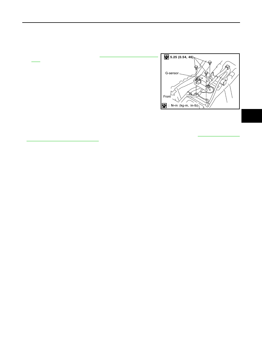
G SENSOR
Removal and Installation
INFOID:0000000001327701
REMOVAL
1.
Remove center console. Refer to
2.
Disconnect G sensor harness connector.
3.
Remove G sensor mounting bolts. Then remove G sensor from
vehicle.
CAUTION:
• Do not drop or strike G sensor, because it has little endurance
to impact.
• Do not use power tool etc., because G sensor is weak for the
impact.
INSTALLATION
Note the following, and install in the reverse order of removal.
CAUTION:
• Do not drop or strike G sensor, because it has little endurance to impact.
• After performing above works, calibrate decel G sensor (AWD models). Refer to
of Decel G Sensor (AWD Models)"
PFIA0602E
BRC-56
< SERVICE INFORMATION >
[VDC/TCS/ABS]
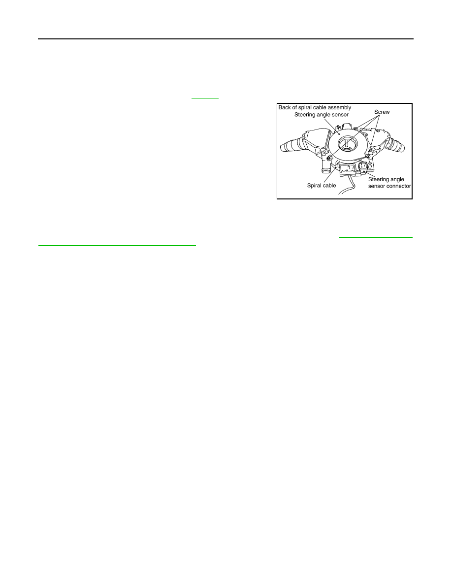
STEERING ANGLE SENSOR
STEERING ANGLE SENSOR
Removal and Installation
INFOID:0000000001327702
REMOVAL
1.
Remove spiral cable assembly. Refer to
2.
Remove steering angle sensor from spiral cable assembly.
INSTALLATION
Installation is the reverse order of removal.
CAUTION:
After work, make sure to adjust neutral position of steering angle sensor. Refer to
of Steering Angle Sensor Neutral Position"
SFIA1404E
CO-1
ENGINE
C
D
E
F
G
H
I
J
K
L
M
SECTION
CO
A
CO
N
O
P
CONTENTS
ENGINE COOLING SYSTEM
VQ35DE
SERVICE INFORMATION . . . . . . .
PRECAUTIONS . . . . . . . . . . . . ...
Precaution for Liquid Gasket . . . . . . . . .....
PREPARATION . . . . . . . . . . . . ...
Special Service Tool . . . . . . . . . . . .....
Commercial Service Tool . . . . . . . . . . ..
OVERHEATING CAUSE ANALYSIS . . . . ..
Troubleshooting Chart . . . . . . . . . . . ...
COOLING SYSTEM . . . . . . . . . . .
Cooling Circuit . . . . . . . . . . . . . . ...
System Chart . . . . . . . . . . . . . . ....
ENGINE COOLANT . . . . . . . . . . ...
Inspection . . . . . . . . . . . . . . . .
Changing Engine Coolant . . . . . . . . . ...
RADIATOR . . . . . . . . . . . . . . .
Component . . . . . . . . . . . . . . . ..
Removal and Installation . . . . . . . . . . .
Checking Radiator Cap . . . . . . . . . . ...
Checking Radiator . . . . . . . . . . . . ...
RADIATOR (ALUMINUM TYPE) . . . . . .
Component . . . . . . . . . . . . . . . ..
Disassembly and Assembly . . . . . . . . .
COOLING FAN . . . . . . . . . . . . ...
Component . . . . . . . . . . . . . . . ..
Removal and Installation . . . . . . . . . . .
Disassembly and Assembly . . . . . . . . .
WATER PUMP . . . . . . . . . . . . ...
Component . . . . . . . . . . . . . . . ..
Removal and Installation . . . . . . . . . . .
WATER INLET AND THERMOSTAT ASSEM-
BLY . . . . . . . . . . . . . . . . .
Component . . . . . . . . . . . . . . . ..
Removal and Installation . . . . . . . . . . .
WATER OUTLET AND WATER PIPING . . ..
Component . . . . . . . . . . . . . . . ..
Removal and Installation . . . . . . . . . . .
SERVICE DATA AND SPECIFICATIONS
(SDS) . . . . . . . . . . . . . . . . .
Standard and Limit . . . . . . . . . . . . ..
VK45DE
SERVICE INFORMATION . . . . . . ...
PRECAUTIONS . . . . . . . . . . . . .
PREPARATION . . . . . . . . . . . . .
Special Service Tool . . . . . . . . . . . .
Commercial Service Tool . . . . . . . . . .
OVERHEATING CAUSE ANALYSIS . . . .
Troubleshooting Chart . . . . . . . . . . . .
COOLING SYSTEM . . . . . . . . . . ..
Cooling Circuit . . . . . . . . . . . . . . .
System Chart . . . . . . . . . . . . . . ...
ENGINE COOLANT . . . . . . . . . . ..
Inspection . . . . . . . . . . . . . . . .
Changing Engine Coolant . . . . . . . . . .
RADIATOR . . . . . . . . . . . . . .
Component . . . . . . . . . . . . . . . ..
Removal and Installation . . . . . . . . . . .
Checking Radiator Cap . . . . . . . . . . ...
Нет комментариевНе стесняйтесь поделиться с нами вашим ценным мнением.
Текст