Infiniti FX35 / FX45. Manual — part 261
BRC-30
< SERVICE INFORMATION >
[VDC/TCS/ABS]
TROUBLE DIAGNOSIS
Note: Serves as EBD warning lamp.
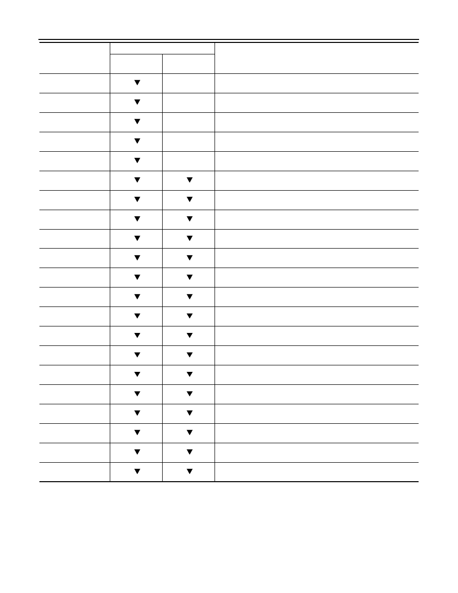
Active Test
INFOID:0000000001327674
CAUTION:
• Do not perform active test while driving vehicle.
• Make sure to completely bleed air from the brake system.
• Active test can not be performed when EBD, ABS, TCS or VDC operation is malfunction.
• ABS and brake warning lamps turn on during the active test.
NOTE:
RR LH IN SOL
(ON/OFF)
×
Rear LH IN ABS solenoid (ON/OFF) status is displayed.
RR LH OUT SOL
(ON/OFF)
×
Rear LH OUT ABS solenoid (ON/OFF) status is displayed.
OFF LAMP
(ON/OFF)
×
OFF Lamp (ON/OFF) status is displayed.
MOTOR RELAY
(ON/OFF)
×
ABS motor relay signal (ON/OFF) status is displayed.
ACTUATOR RLY
(ON/OFF)
×
ABS actuator relay signal (ON/OFF) status is displayed.
CV1
(ON/OFF)
Primary side switch-over solenoid valve 1 (cut valve 1) (ON/OFF) status
is displayed.
CV2
(ON/OFF)
Secondary side switch-over solenoid valve 2 (cut-valve 2) (ON/OFF)
status is displayed.
SV1
(ON/OFF)
Primary side switch-over solenoid valve 1 (suction valve 1) (ON/OFF)
status is displayed.
SV2
(ON/OFF)
Secondary side switch-over solenoid valve 2 (suction valve 2) (ON/
OFF) status is displayed.
VDC FAIL SIG
(ON/OFF)
VDC fail signal (ON/OFF) status is displayed.
TCS FAIL SIG
(ON/OFF)
TCS fail signal (ON/OFF) status is displayed.
ABS FAIL SIG
(ON/OFF)
ABS fail signal (ON/OFF) status is displayed.
EBD FAIL SIG
(ON/OFF)
EBD fail signal (ON/OFF) status is displayed.
EBD SIGNAL
(ON/OFF)
EBD operation (ON/OFF) status is displayed.
ABS SIGNAL
(ON/OFF)
ABS operation (ON/OFF) status is displayed.
TCS SIGNAL
(ON/OFF)
TCS operation (ON/OFF) status is displayed.
VDC SIGNAL
(ON/OFF)
VDC operation (ON/OFF) status is displayed.
EBD WARN LAMP
(ON/OFF)
Brake warning lamp (ON/OFF) status is displayed. (Note)
CRANKING SIG
(ON/OFF)
Cranking condition (ON/OFF) status is displayed.
4WD FAIL REQ
(ON/OFF)
AWD fail-safe signal (ON/OFF) status is displayed.
2WD/4WD
(2WD/4WD)
Distinguish 2WD and AWD
Item
(Unit)
Data monitor item selection
Remarks
ECU INPUT
SIGNALS
MAIN
SIGNALS
TROUBLE DIAGNOSIS
BRC-31
< SERVICE INFORMATION >
[VDC/TCS/ABS]
C
D
E
G
H
I
J
K
L
M
A
B
BRC
N
O
P
• When active test is performed while depressing, the pedal depression amount will change. This is normal.
• “TEST IS STOPPED” is displayed 10 seconds after operation start.
• After “TEST IS STOPPED” is displayed, touch “BACK” and perform test again.
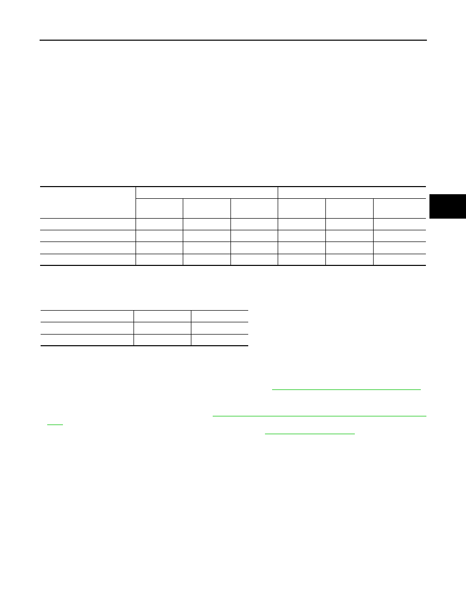
TEST ITEM
Solenoid Valve
NOTE:
The example shown is for the front right wheel. The procedure for the other wheels is the same as given
below.
• When performing an active test of the ABS function, select the main item for each test item. In addition,
when performing an active test of the VDC/TCS function, select the item menu for each test item.
• For the ABS solenoid valve, touch “UP” “KEEP” “DOWN”, and for the ABS solenoid valve (ACT), touch “UP”
“ACTUATOR UP” “ACTUATOR KEEP”, and check to make sure that all solenoid valve (in, out) are operating
as given in the table below.
*: ON for 1 to 2 seconds after the touch, and then OFF
ABS Motor
Touch “ON” and “OFF” on the screen. Make sure ABS motor relay operates as shown in table below.
For Fast and Accurate Diagnosis
INFOID:0000000001327675
PRECAUTIONS FOR DIAGNOSIS
• Before performing diagnosis, always read precautions. Refer to
BRC-13, "How to Proceed with Diagnosis"
.
• If ABS actuator and electric unit (control unit), steering angle sensor, steering system parts or suspension
system parts have been replaced, or if alignment has been adjusted, be sure to adjust neutral position of
steering angle sensor before driving. Refer to
BRC-8, "Adjustment of Steering Angle Sensor Neutral Posi-
• After diagnosis is finished, be sure to erase memory. Refer to
• When checking continuity and voltage between units, be sure to check for disconnection, looseness, bend,
or collapse of connector terminals. If any malfunction is found, repair or replace connector terminals.
• For intermittent symptoms, possible cause is malfunction in harness, harness connector, or terminals. Move
harness, harness connector, and terminals to check for poor connections.
• If a circuit tester is used for the check, be careful not to forcibly extend any connector terminal.
• To use CONSULT-III to perform self-diagnosis of ABS actuator and electric unit (control unit), active tests, or
work support, first stop work, then connect CONSULT-III and select “ABS”.
• While self-diagnostic results of CONSULT-III shows malfunction, if CONSULT-III active test is performed, an
engine system error may be indicated. In this case, start engine to resume the normal screen.
• VDC/TCS/ABS system electronically controls brake operation and engine output. The following symptoms
may be caused by normal operations:
Operation
ABS solenoid valve
ABS solenoid valve (ACT)
UP
KEEP
DOWN
UP
ACTUATOR
UP
ACTUATOR
KEEP
FR RH IN SOL
OFF
ON
ON
OFF
OFF
OFF
FR RH OUT SOL
OFF
OFF
ON*
OFF
OFF
OFF
CV 1
OFF
OFF
OFF
OFF
ON
ON
SV 1
OFF
OFF
OFF
OFF
ON*
OFF
Operation
ON
OFF
MOTOR RELAY
ON
OFF
ACTUATOR RLY
ON
ON

BRC-32
< SERVICE INFORMATION >
[VDC/TCS/ABS]
TROUBLE DIAGNOSIS
Basic Inspection
INFOID:0000000001327676
BRAKE FLUID AMOUNT, LEAKS, AND BRAKE PADS INSPECTION
1.
Check fluid level in the brake reservoir tank. If fluid level is low, refill brake fluid.
2.
Check brake piping and around ABS actuator and electric unit (control unit) for leaks. If there is leaking or
oozing fluid, check the following items.
• If ABS actuator and electric unit (control unit) connection is loose, tighten piping to the specified torque
and re-perform the leak inspection to make sure there are no leaks.
• If there is damage to the connection flare nut or ABS actuator and electric unit (control unit) screw,
replace the damaged part and re-perform the leak inspection to make sure there are no leaks.
• When there is fluid leaking or oozing from a part other than ABS actuator and electric unit (control unit)
connection, if fluid is just oozing out, use a clean cloth to wipe off the oozing fluid and re-check for leaks.
If fluid is still oozing out, replace the damaged part.
• When there is fluid leaking or oozing at ABS actuator and electric unit (control unit), if fluid is just oozing
out, use a clean cloth to wipe off oozing fluid and re-check for leaks. If fluid is still oozing out, replace
ABS actuator and electric unit (control unit) body.
CAUTION:
ABS actuator and electric unit (control unit) body can not be disassembled.
3.
Check brake pad degree of wear. Refer to
BR-18, "On-Vehicle Inspection"
in “Front Disc Brake” and
in “Rear Disc Brake”
POWER SYSTEM TERMINAL LOOSENESS AND BATTERY INSPECTION
Make sure battery positive cable, negative cable and ground connection are not loose. If looseness is
detected, tighten the cables. In addition, check the battery voltage to make sure it has not dropped and alter-
nator is normal.
ABS WARNING LAMP, VDC OFF INDICATOR LAMP, SLIP INDICATOR LAMP AND BRAKE WARN-
ING LAMP INSPECTION
Symptom
Symptom description
Result
Motor operation noise
This is noise of motor inside ABS actuator and electric unit (control unit).
Slight noise may occur during VDC, TCS, and ABS operation.
Normal
When the vehicle speed goes over 20 km/h (12.5 MPH), motor and valves
operating noise may be heard. It happens only once after ignition switch is
ON. This is a normal status of the system operation check.
System operation check noise
When engine starts, slight “click” noise may be heard from engine room.
This is normal and is part of system operation check.
Normal
VDC/TCS operation
(SLIP indicator lamp blinking)
TCS may activate momentarily if wheel speed changes when driving over
location where friction coefficient varies, when up/downshifting, or when ful-
ly depressing accelerator pedal.
Normal
Cancel the VDC/TCS
function for the inspec-
tion on a chassis dyna-
mometer.
For inspection of speedometer or other instruments, press VDC OFF switch
to turn VDC/TCS function off.
When accelerator pedal is depressed on a chassis dynamometer (fixed
front-wheel type), vehicle speed will not increase. This is not normal. It is re-
sult of TCS being activated by stationary front wheels. Warning lamp may
also illuminate to indicate “sensor system error”. This is also normal, and is
the result of the stationary front wheels being detected. To be certain, restart
engine, and drive vehicle at 30 km/h (19 MPH) or more. Make sure warning
lamp does not illuminate.
ABS operation
(Longer stopping distance)
On roads with low friction coefficients, such as snowy roads or gravel roads,
vehicles with ABS may require a longer stopping distance. Therefore, when
driving on such roads, avoid overconfidence and keep speed sufficiently
low.
Normal
Insufficient feeling of accelera-
tion
Depending on road conditions, driver may feel that feeling of acceleration is
insufficient. This is because traction control, which controls engine and
brakes to achieve optimal traction, has the highest priority (for safety). As a
result, there may be times when acceleration is slightly less than usual for
the same accelerator pedal operation.
Normal

TROUBLE DIAGNOSIS
BRC-33
< SERVICE INFORMATION >
[VDC/TCS/ABS]
C
D
E
G
H
I
J
K
L
M
A
B
BRC
N
O
P
×
: ON
–: OFF
Note 1:Brake warning lamp will turn on in case of operating parking brake (switch turned on) or of actuating brake fluid level switch
(brake fluid is insufficient).
Note 2:After starting engine, turn OFF.
1.
Make sure ABS warning lamp, VDC OFF indicator lamp (when VDC OFF switch is OFF), and SLIP indica-
tor lamp turn on approximately 2 second, and brake warning lamp turns on when ignition switch is turned
ON. If they do not, check VDC OFF indicator lamp and then VDC OFF switch. Refer to
. Check CAN communications. Refer to “CAN Communication Inspection”. If there are no
errors with VDC OFF switch and CAN communication system, check combination meter. Refer to
2.
Make sure ABS warning lamp, VDC OFF indicator lamp, SLIP indicator lamp turn off approximately 2 sec-
ond after turn ignition switch ON, and brake warning lamp turns off after engine starts. If lamps do not turn
off, perform self-diagnosis.
3.
With engine running, make sure VDC OFF indicator lamp turns on and off when VDC OFF switch is
turned ON and OFF. If indicator lamp status does not correspond to switch operation, check the VDC OFF
switch system. Refer to
BRC-48, "Component Inspection"
.
4.
Make sure ABS warning lamp, VDC OFF indicator lamp, and SLIP indicator lamp turn off 2 seconds after
engine is started. If ABS warning lamp, VDC OFF indicator lamp, and SLIP indicator lamp have not turned
off 10 seconds after engine has been started, perform self-diagnosis of ABS actuator and electric unit
(control unit).
5.
After performing the self-diagnosis, be sure to erase the error memory. Refer to
.
NOTE:
Brake warning lamp will turn ON in case of parking brake operation (when switch is ON) or of brake fluid level
switch should not stay “ON” position.
Condition
ABS warning
lamp
VDC OFF in-
dicator lamp
SLIP indicator
lamp
Brake warning
lamp (Note 1)
Remarks
Ignition switch OFF.
–
–
–
—
—
Approx. 2 seconds after ignition
switch is turned ON.
×
×
×
×
(Note 2)
—
Approx. 2 seconds later after ig-
nition switch ON.
–
–
–
×
(Note 2)
Go out 2 seconds after igni-
tion switch is turned ON.
VDC OFF switch is turned ON.
(VDC/TCS function is OFF.)
–
×
–
—
—
VDC/TCS/ABS error.
×
×
×
—
There is an ABS actuator
and electric unit (control unit)
error. (Power, ground or sys-
tem malfunction)
When VDC/TCS is not function-
ing normally.
–
×
×
—
—
EBD error.
×
×
×
×
—
Нет комментариевНе стесняйтесь поделиться с нами вашим ценным мнением.
Текст