Infiniti FX35 / FX45. Manual — part 262

BRC-34
< SERVICE INFORMATION >
[VDC/TCS/ABS]
TROUBLE DIAGNOSIS FOR SYSTEM
TROUBLE DIAGNOSIS FOR SYSTEM
DTC C1101 RR RH SENSOR-1
INFOID:0000000001327677
After using the CONSULT-III SELF-DIAG RESULTS to determine the location of the malfunctioning wheel sen-
sor, check all areas to determine the component to be replaced.
CAUTION:
• Do not measure the resistance value and also voltage between sensor terminal with tester etc.,
because sensor is an active sensor.
• Do not expand terminal of connector with a tester terminal stick, when it does the inspection with
tester.
INSPECTION PROCEDURE
1.
CHECK TIRE
Check air pressure, wear and size.
Are air pressure, wear, and size within the standard values?
YES
>> GO TO 2.
NO
>> Adjust air pressure, or replace tire.
2.
CHECK SENSOR AND SENSOR ROTOR
• Check condition of the sensor mount (for looseness, etc.).
• Check surface of front sensor rotor rubber for damage.
• Check rear sensor rotor for damage.
OK or NG
OK
>> GO TO 3.
NG
>> Repair sensor mount or replace sensor rotor.
3.
CHECK SELF-DIAGNOSTIC RESULTS
Check the self-diagnostic results.
Is the above displayed in the self-diagnosis display items?
YES
>> GO TO 4.
NO
>> INSPECTION END
4.
CHECK CONNECTOR
1.
Disconnect ABS actuator and electric unit (control unit) connector and malfunctioning wheel sensor con-
nector E46 (FR-LH), E33 (FR-RH) or B69 (RR). Check terminal for deformation, open circuit, poor con-
tact, etc., and repair or replace if any malfunctioning condition is found.
2.
Reconnect connectors, drive at a speed of approximately 30 km/h (19 MPH) or more for approximately 1
minute, and perform self-diagnosis.
OK or NG
OK
>> Connector terminal contact is loose, damaged, open or shorted.
NG
>> GO TO 5.
5.
CHECK WHEEL SENSOR HARNESS
Self-diagnostic results
FR RH SENSOR-1,-2
FR LH SENSOR- 1,-2
RR RH SENSOR-1,-2
RR LH SENSOR-1,- 2
ABS SENSOR [ABNORMAL SIGNAL]

TROUBLE DIAGNOSIS FOR SYSTEM
BRC-35
< SERVICE INFORMATION >
[VDC/TCS/ABS]
C
D
E
G
H
I
J
K
L
M
A
B
BRC
N
O
P
1.
Turn ignition switch OFF and disconnect malfunctioning wheel
sensor connector E46 (FR-LH), E33 (FR-RH) or B69 (RR) and
ABS actuator and electric unit (control unit) connector E56.
2.
Check continuity between terminals. (Also check the continuity
when steering wheel is turned right and left and when sensor
harness inside wheel well is moved.)
OK or NG
OK
>> GO TO 6.
NG
>> Repair or replace harness and connector that have malfunction.
6.
CHECK WHEEL SENSOR POWER SUPPLY CIRCUIT
1.
Disconnect malfunctioning wheel sensor connector.
2.
Turn ignition switch ON and check voltage between wheel sen-
sor harness connector power supply terminal and ground.
OK or NG?
OK
>> Replace wheel sensor.
NG
>> Replace ABS actuator and electric unit (control unit).
DTC C1102 RR LH SENSOR-1
INFOID:0000000001569691
BRC-34, "DTC C1101 RR RH SENSOR-1"
DTC C1103 FR RH SENSOR-1
INFOID:0000000001569692
BRC-34, "DTC C1101 RR RH SENSOR-1"
DTC C1104 FR LH SENSOR-1
INFOID:0000000001569693
BRC-34, "DTC C1101 RR RH SENSOR-1"
SFIA1186E
Power supply circuit
Signal circuit
Ground circuit
Wheel
ABS actuator
and electric unit
(control unit)
Wheel sensor
ABS actuator
and electric unit
(control unit)
Wheel sensor
ABS actuator and elec-
tric unit (control unit)
(signal)
ABS actuator and elec-
tric unit (control unit)
(ground)
Front RH
34
1
33
2
33, 34
16, 47
Front LH
45
1
46
2
45, 46
Rear RH
43
1
42
2
43, 42
Rear LH
36
3
37
4
36, 37
Power supply circuit
: Continuity should exist.
Signal circuit
: Continuity should exist.
Ground circuit
: Continuity should not exist.
Wheel
Wheel sensor
Ground
Voltage
Front RH
1
—
8 V or more
Front LH
1
Rear RH
1
Rear LH
3
SFIA3364E
BRC-36
< SERVICE INFORMATION >
[VDC/TCS/ABS]
TROUBLE DIAGNOSIS FOR SYSTEM
DTC C1105 RR RH SENSOR-2
INFOID:0000000001569694
BRC-34, "DTC C1101 RR RH SENSOR-1"
DTC C1106 RR LH SENSOR-2
INFOID:0000000001569695
BRC-34, "DTC C1101 RR RH SENSOR-1"
DTC C1107 FR RH SENSOR-2
INFOID:0000000001569696
BRC-34, "DTC C1101 RR RH SENSOR-1"
DTC C1108 FR LH SENSOR-2
INFOID:0000000001569697
BRC-34, "DTC C1101 RR RH SENSOR-1"
DTC C1109 BATTERY VOLTAGE [ABNORMAL]
INFOID:0000000001327685
INSPECTION PROCEDURE
1.
CHECK SELF-DIAGNOSTIC RESULTS (1)
Check the self-diagnostic results.
Does “BATTERY VOLTAGE” appear in self-diagnostic results display?
YES
>> GO TO 2.
NO
>> INSPECTION END
2.
CHECK SELF-DIAGNOSTIC RESULTS (2)
1.
Disconnect ABS actuator and electric unit (control unit) connector. Then reconnect it securely.
2.
Perform self-diagnosis.
Do any self-diagnosis item appear?
YES
>> GO TO 3.
NO
>> Poor connection. Repair or replace connector.
3.
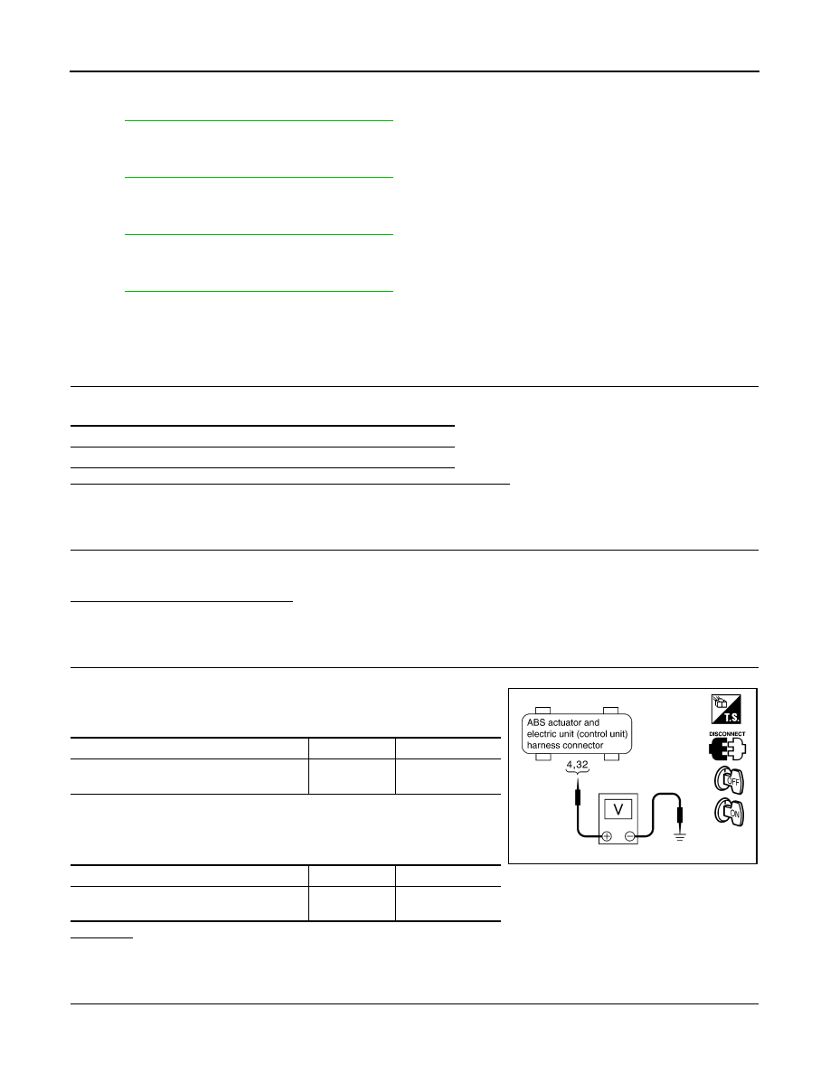
CHECK ABS ACTUATOR AND ELECTRIC UNIT (CONTROL UNIT) POWER SUPPLY CIRCUIT (1)
1.
Disconnect ABS actuator and electric unit (control unit) connector E56.
2.
Turn ignition switch OFF. Check voltage between ABS actuator
and electric unit (control unit) harness connector and ground.
3.
Turn ignition switch ON (but do not start engine). Check voltage
between ABS actuator and electric unit (control unit) harness
connector and ground.
OK or NG
OK
>> GO TO 4.
NG
>> GO TO 5.
4.
CHECK ABS ACTUATOR AND ELECTRIC UNIT (CONTROL UNIT) GROUND CIRCUIT
Self-diagnostic results
BATTERY VOLTAGE [ABNORMAL]
ABS actuator and electric unit (control unit)
Ground
Voltage
32
—
Battery voltage
(Approx. 12 V)
ABS actuator and electric unit (control unit)
Ground
Voltage
4
—
Battery voltage
(Approx. 12 V)
SFIA1200E

TROUBLE DIAGNOSIS FOR SYSTEM
BRC-37
< SERVICE INFORMATION >
[VDC/TCS/ABS]
C
D
E
G
H
I
J
K
L
M
A
B
BRC
N
O
P
Check ABS actuator and electric unit (control unit) ground circuit.
OK or NG
OK
>> Perform ABS actuator and electric unit (control unit) self-
diagnosis again.
NG
>> Repair or replace harness or connectors.
5.
CHECK ABS ACTUATOR AND ELECTRIC UNIT (CONTROL UNIT) POWER SUPPLY CIRCUIT (2)
1.
Check fuse 10 A (terminal 4) and 30 A (terminal 32).
2.
Turn ignition switch OFF and check continuity between battery
positive terminal and ABS actuator and electric unit (control unit)
harness connector E56.
OK or NG
OK
>> Check for non-standard conditions in battery (terminal
looseness, low voltage, etc.) and alternator.
NG
>> • Replace fuse 10 A or 30 A.
• Open or short in harness.
DTC C1110 CONTROLLER FAILURE
INFOID:0000000001327679
INSPECTION PROCEDURE
1.
CHECK SELF-DIAGNOSTIC RESULTS
Check the self-diagnostic results.
Is the above displayed in the self-diagnosis display items?
YES
>> Replace ABS actuator and electric unit (control unit). Perform the self-diagnosis again.
NO
>> INSPECTION END
DTC C1111 PUMP MOTOR
INFOID:0000000001327684
INSPECTION PROCEDURE
1.
CHECK SELF-DIAGNOSTIC RESULTS (1)
Check the self-diagnostic results.
Is the above displayed in the self-diagnostic display items?
YES
>> GO TO 2.
NO
>> Inspection is completed.
2.
CHECK SELF-DIAGNOSTIC RESULTS (2)
ABS actuator and electric unit (control unit)
Ground
Continuity
16
—
Yes
SFIA1434E
ABS actuator and electric unit
(control unit)
Battery positive terminal
Continuity
4, 32
—
Yes
SFIA1435E
Self-diagnostic results
CONTROLLER FAILURE
VARIANT CODING
Self-diagnostic results
PUMP MOTOR
ACTUATOR RLY
Нет комментариевНе стесняйтесь поделиться с нами вашим ценным мнением.
Текст