Infiniti FX35 / FX45. Manual — part 70
AT-208
< SERVICE INFORMATION >
A/T SHIFT LOCK SYSTEM
A/T SHIFT LOCK SYSTEM
Description
INFOID:0000000001327387
• The mechanical key interlock mechanism also operates as a shift lock:
With the ignition switch turned to ON, the selector lever cannot be shifted from “P” position to any other posi-
tion unless the brake pedal is depressed.
With the key removed, the selector lever cannot be shifted from “P” position to any other position.
The key cannot be removed unless the selector lever is placed in “P” position.
• The shift lock and key interlock mechanisms are controlled by the ON-OFF operation of the shift lock sole-
noid and by the operation of the rotator and slider located inside the key cylinder.
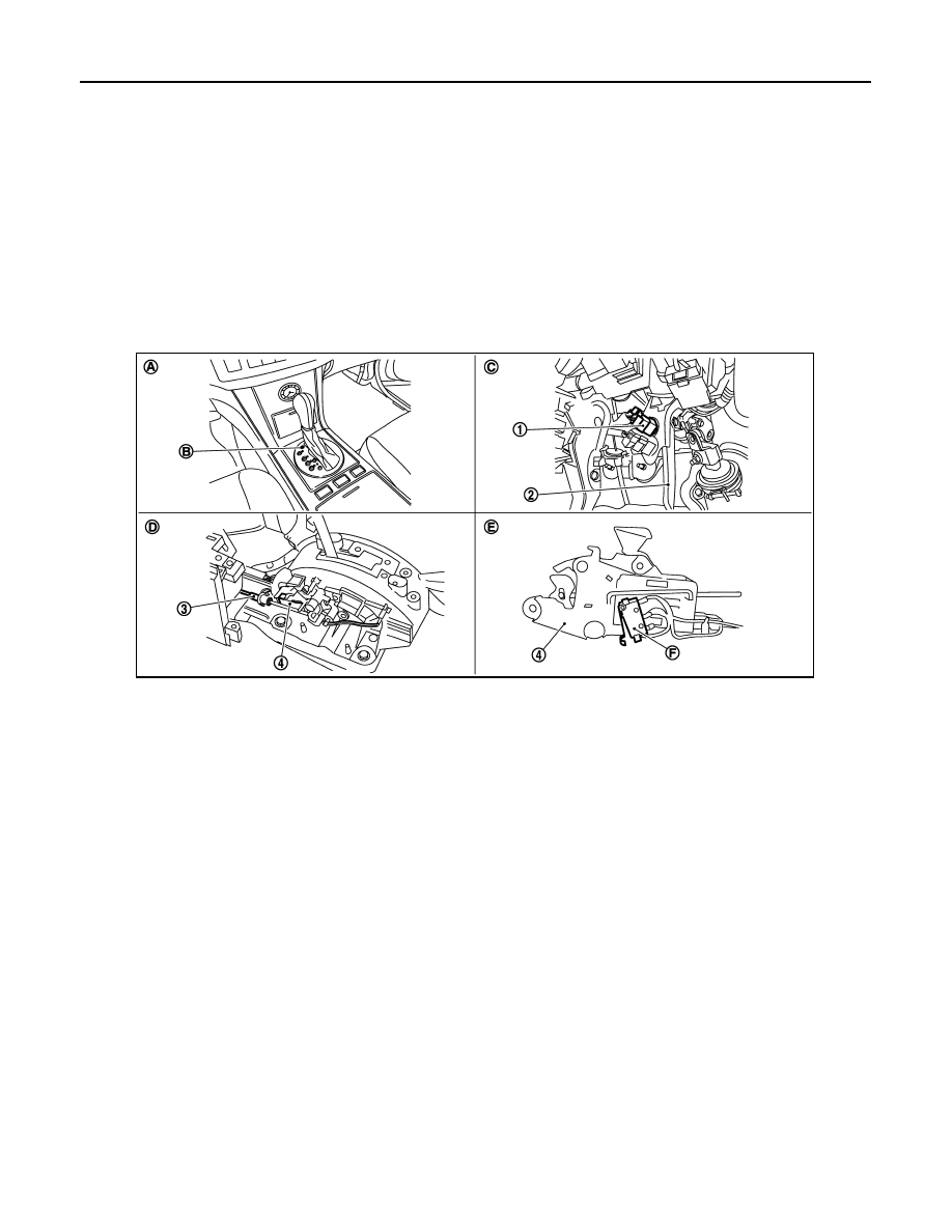
Shift Lock System Electrical Parts Location
INFOID:0000000001327388
1.
Stop lamp switch
2.
Brake pedal
3.
Key interlock cable
4.
Shift lock solenoid
A.
Center console assembly
B.
Shift lock release button
C.
Brake pedal, upper
D.
Control device assembly
E.
Shift lock solenoid, reverse side
F.
Park position switch
SCIA8107E
A/T SHIFT LOCK SYSTEM
AT-209
< SERVICE INFORMATION >
D
E
F
G
H
I
J
K
L
M
A
B
AT
N
O
P
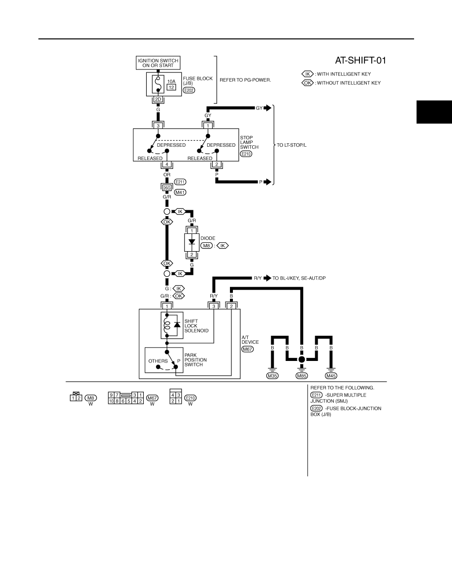
Wiring Diagram - AT - SHIFT
INFOID:0000000001327389
Diagnosis Procedure
INFOID:0000000001327390
SYMPTOM 1:
• Selector lever cannot be moved from “P” position with key in ON position and brake pedal applied.
• Selector lever can be moved from “P” position with key in ON position and brake pedal released.
• Selector lever can be moved from “P” position when key is removed from key cylinder.
SYMPTOM 2:
TCWM0589E
AT-210
< SERVICE INFORMATION >
A/T SHIFT LOCK SYSTEM
• Ignition key cannot be removed when selector lever is set to “P” position.
• Ignition key can be removed when selector lever is set to any position except “P” position.
1.
CHECK KEY INTERLOCK CABLE
Check the key interlock cable for damage.
OK or NG
OK
>> GO TO 2.
NG
>> Repair or replace key interlock cable. Refer to
.
2.
CHECK SELECTOR LEVER POSITION
Check the selector lever position for damage. Refer to
AT-207, "Checking of A/T Position"
OK or NG
OK
>> GO TO 3.
NG
>> Adjust A/T position. Refer to
AT-207, "Adjustment of A/T Position"
.
3.
CHECK SHIFT LOCK SOLENOID AND PARK POSITION SWITCH
1.
Connect A/T device harness connector.
2.
Turn ignition switch ON.
3.
Selector lever is set in “P” position.
4.
Check operation.
OK or NG
OK
>> INSPECTION END
NG
>> GO TO 4.
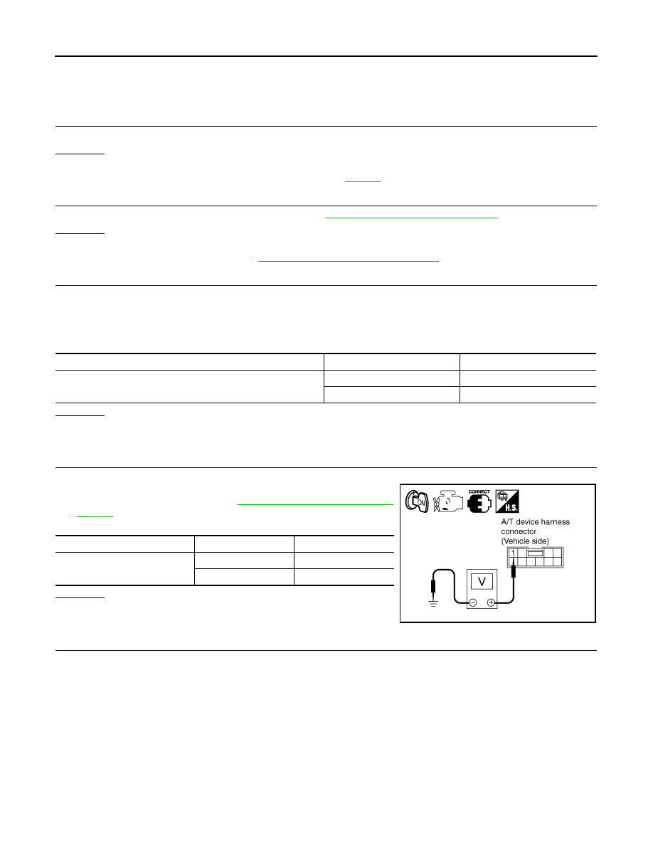
4.
CHECK POWER SOURCE
1.
Turn ignition switch ON.
2.
Check the voltage between A/T device harness connector M67
terminal 1 and ground. Refer to
AT-209, "Wiring Diagram - AT -
OK or NG
OK
>> GO TO 7.
NG
>> GO TO 5.
5.
CHECK STOP LAMP SWITCH
1.
Turn ignition switch OFF.
2.
Disconnect stop lamp switch harness connector.
Condition
Brake pedal
Operation
When ignition switch is turned to ON and selector lever is set in
“P” position.
Depressed
Yes
Released
No
Condition
Brake pedal
Data (Approx.)
When ignition switch is turned to
ON.
Depressed
Battery voltage
Released
0 V
SCIA2122E
A/T SHIFT LOCK SYSTEM
AT-211
< SERVICE INFORMATION >
D
E
F
G
H
I
J
K
L
M
A
B
AT
N
O
P
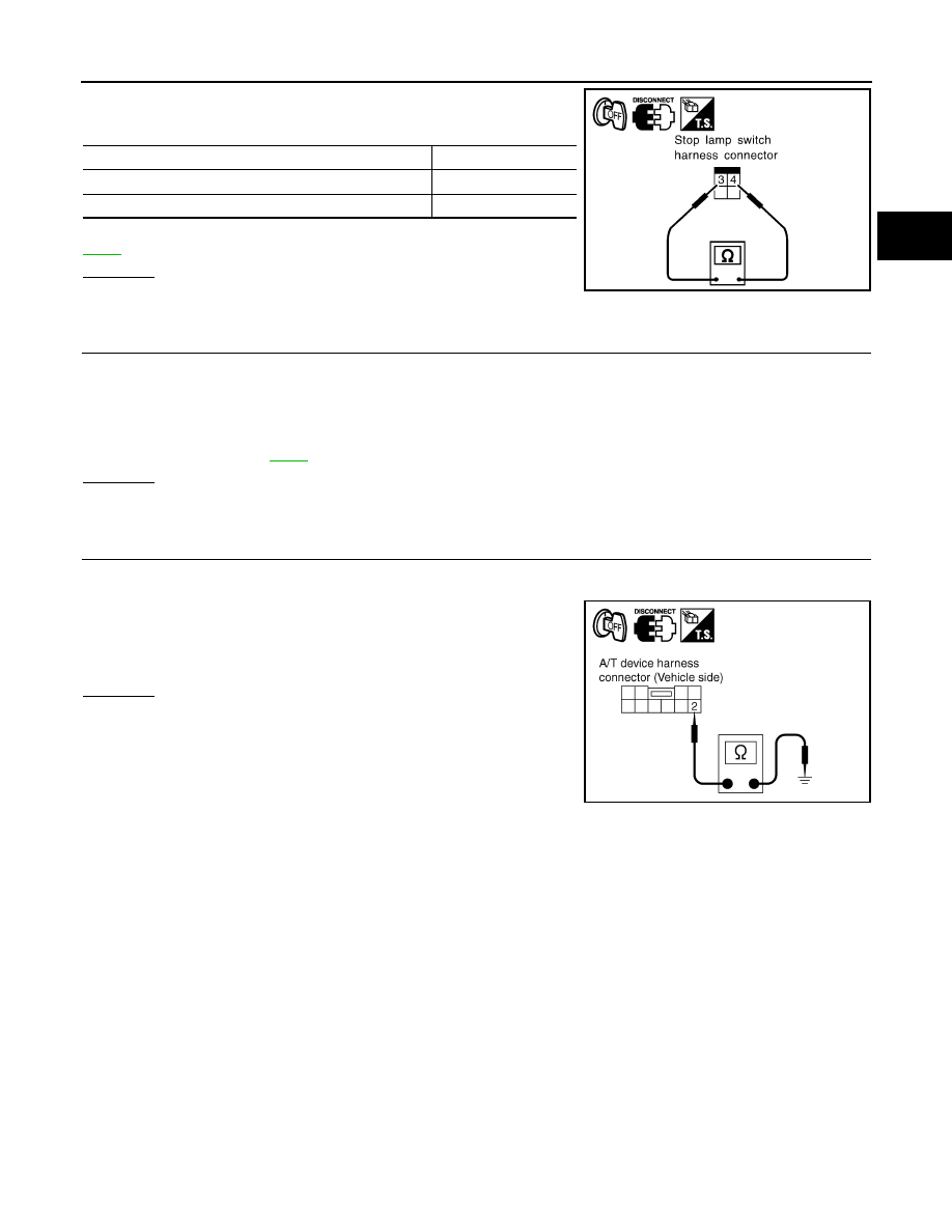
3.
Check continuity between stop lamp switch harness connector
E210 terminals 3 and 4.
Check stop lamp switch after adjusting brake pedal — refer to
OK or NG
OK
>> GO TO 6.
NG
>> Repair or replace damaged parts.
6.
DETECT MALFUNCTIONING ITEM
Check the following items. If any items are damaged, repair or replace damaged parts.
• Harness for short or open between ignition switch and stop lamp switch harness connector E210 terminal 3.
• Harness for short or open between stop lamp switch harness connector E210 terminal 4 and A/T device har-
ness connector M67 terminal 1.
• 10 A fuse [No.12, located in the fuse block (J/B)].
• Ignition switch, Refer to
.
OK or NG
OK
>> INSPECTION END
NG
>> Repair or replace damaged parts.
7.
CHECK GROUND CIRCUIT
1.
Turn ignition switch OFF.
2.
Disconnect A/T device harness connector.
3.
Check continuity between A/T device harness connector M67
terminal 2 and ground.
OK or NG
OK
>> Replace shift lock solenoid and park position switch
assembly.
NG
>> Repair open circuit in harness or connectors.
Condition
Continuity
When brake pedal is depressed
Yes
When brake pedal is released
No
SCIA2126E
Continuity should exist.
SCIA2125E
Нет комментариевНе стесняйтесь поделиться с нами вашим ценным мнением.
Текст