Infiniti FX35 / FX45. Manual — part 71
AT-212
< SERVICE INFORMATION >
KEY INTERLOCK CABLE
KEY INTERLOCK CABLE
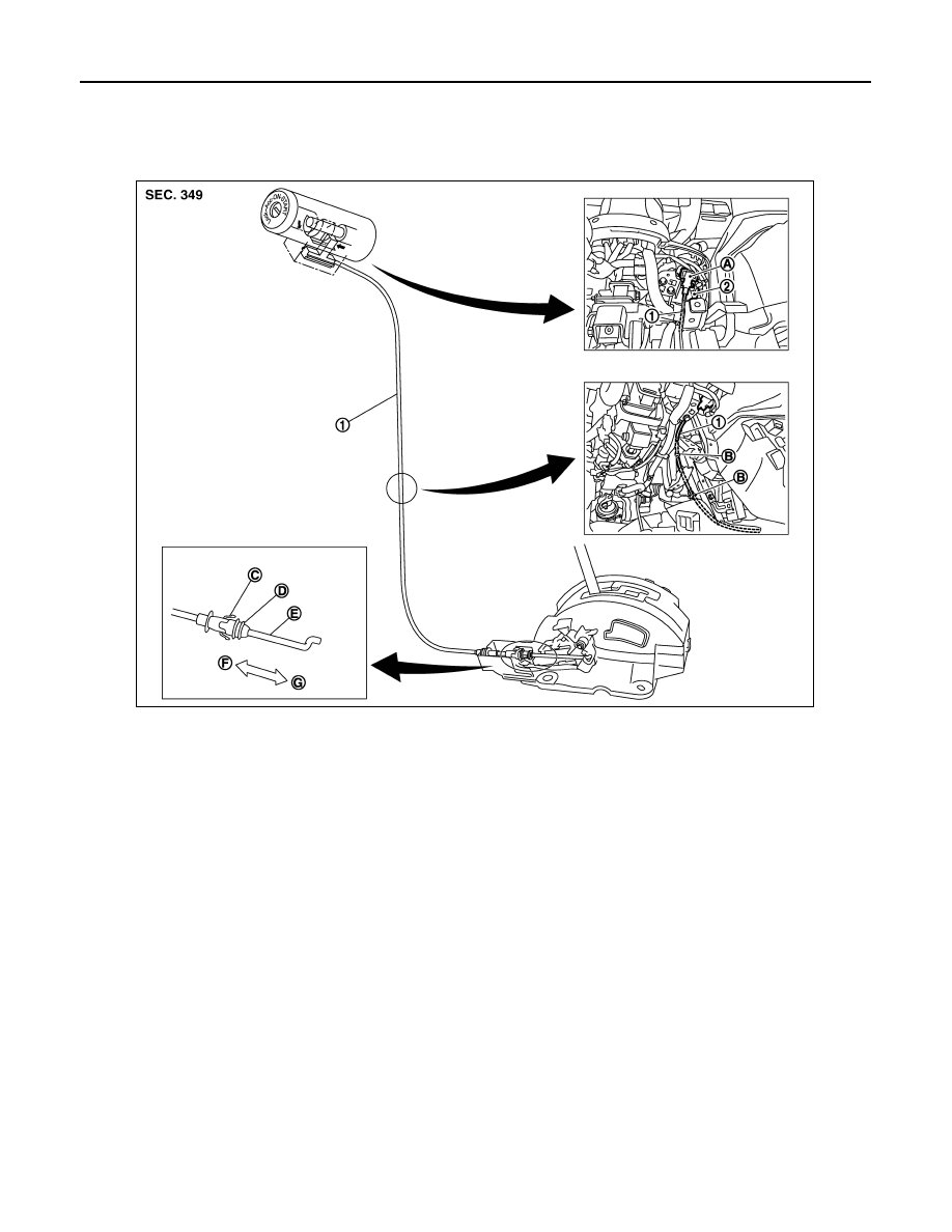
Component
INFOID:0000000001327391
CAUTION:
• Install key interlock cable in such a way that it will not be damaged by sharp bends, twists or interfer-
ence with adjacent parts.
• After installing key interlock cable to control device, make sure that casing cap and bracket are
firmly secured in their positions. If casing cap be removed with an external load of less than 39.2 N
(4.0 kg, 8.8 lb), replace key interlock cable with new one.
Removal and Installation
INFOID:0000000001327392
REMOVAL
1.
Key interlock cable
2.
Key cylinder
A.
Holder
B.
Clip
C.
Slider
D.
Adjuster holder
E.
Interlock rod
F.
Unlock
G.
Lock
SCIA7755E
KEY INTERLOCK CABLE
AT-213
< SERVICE INFORMATION >
D
E
F
G
H
I
J
K
L
M
A
B
AT
N
O
P
1.
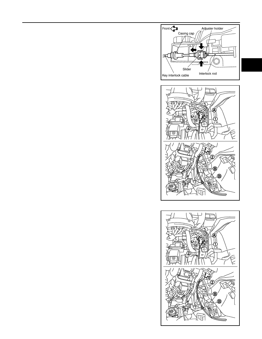
Unlock slider by squeezing lock tabs on slider from adjuster
holder.
2.
Remove casing cap from bracket of control device assembly
and remove interlock rod from adjuster holder.
3.
Remove holder (A) from key cylinder (1) and remove key inter-
lock cable (2).
(B) : Clips
INSTALLATION
1.
Set key interlock cable (2) to key cylinder (1) and install holder
(A).
2.
Clamp key interlock cable (2) and fix to key interlock cable (2)
with clips (B).
3.
Turn ignition key to “LOCK” position.
4.
Set selector lever to “P” position.
SCIA1230E
SCIA7761E
SCIA7761E
AT-214
< SERVICE INFORMATION >
KEY INTERLOCK CABLE
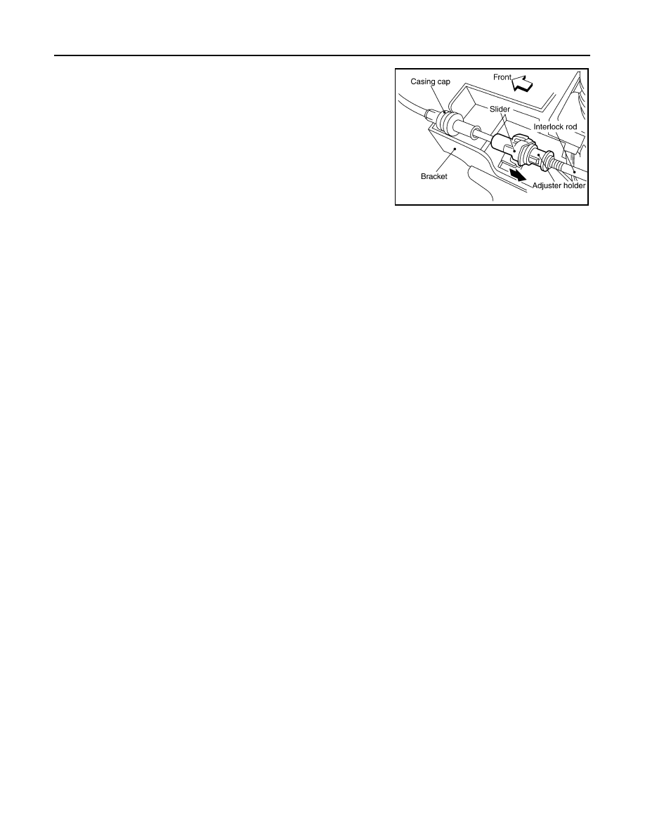
5.
Insert interlock rod into adjuster holder.
6.
Install casing cap to bracket.
7.
Move slider in order to fix adjuster holder to interlock rod.
CAUTION:
Do not touch adjacent parts of key interlock cable when
slider is being held.
Insert slider into key interlock rod straightly.
SCIA1232E

ON-VEHICLE SERVICE
AT-215
< SERVICE INFORMATION >
D
E
F
G
H
I
J
K
L
M
A
B
AT
N
O
P
ON-VEHICLE SERVICE
Control Valve with TCM and A/T Fluid Temperature Sensor 2
INFOID:0000000001327393
COMPONENTS
CONTROL VALVE WITH TCM ASSEMBLY REMOVAL AND INSTALLATION
Removal
1.
Disconnect the battery cable from the negative terminal.
2.
Drain ATF through drain plug.
3.
Remove front cross bar. Refer to
FSU-6, "Removal and Installation"
.
4.
Disconnect heated oxygen sensor 2 harness connector.
5.
Disconnect A/T assembly harness connector.
1.
A/T
2.
Snap ring
3.
Sub-harness
4.
Control valve with TCM
5.
Bracket
6.
A/T fluid temperature sensor 2
7.
Oil pan gasket
8.
Clip
9.
Bracket (VK45DE)
10. Bracket (VK45DE)
11.
Oil pan mounting bolt
12. Oil pan
13. Magnet
14. Drain plug
15. Drain plug gasket
16. Terminal cord assembly
17. O-ring
Refer to GI section to make sure icons (symbol marks) in the figure. Refer to
SCIA8045E
Нет комментариевНе стесняйтесь поделиться с нами вашим ценным мнением.
Текст