Infiniti FX35 / FX45. Manual — part 42
AT-96
< SERVICE INFORMATION >
DTC U1000 CAN COMMUNICATION LINE
TCM terminals and data are reference value. Measured between each terminal and ground.
Diagnosis Procedure
INFOID:0000000001327170
1.
CHECK CAN COMMUNICATION CIRCUIT
With CONSULT-III
1.
Turn ignition switch ON and start engine.
2.
Select “SELF-DIAG RESULTS” mode for “TRANSMISSION” with CONSULT-III.
Is the “U1000 CAN COMM CIRCUIT” indicated?
YES
>> Go to LAN section. Refer to
LAN-43, "CAN System Specification Chart"
NO
>> INSPECTION END
Terminal
Wire
color
Item
Condition
Data (Approx.)
3
L
CAN-H
–
–
8
P
CAN-L
–
–
DTC P0615 START SIGNAL CIRCUIT
AT-97
< SERVICE INFORMATION >
D
E
F
G
H
I
J
K
L
M
A
B
AT
N
O
P
DTC P0615 START SIGNAL CIRCUIT
Description
INFOID:0000000001327171
TCM prohibits cranking other than at “P” or “N” position.
CONSULT-III Reference Value in Data Monitor Mode
INFOID:0000000001327172
On Board Diagnosis Logic
INFOID:0000000001327173
Diagnostic trouble code “P0615 STARTER RELAY/CIRC” with CONSULT-III or 14th judgement flicker without
CONSULT-III is detected when starter relay is switched ON other than at “P” or “N” position. (Or when
switched OFF at “P” or “N” position).
Possible Cause
INFOID:0000000001327174
• Harness or connectors
(Starter relay and TCM circuit is open or shorted.)
• Starter relay circuit
DTC Confirmation Procedure
INFOID:0000000001327175
CAUTION:
Always drive vehicle at a safe speed.
NOTE:
If “DTC Confirmation Procedure” has been previously performed, always turn ignition switch OFF and
wait at least 10 seconds before performing the next test.
After the repair, perform the following procedure to confirm the malfunction is eliminated.
WITH CONSULT-III
1.
Turn ignition switch ON.
2.
Select “SELECTION FROM MENU” in “DATA MONITOR” mode for “TRANSMISSION” with CONSULT-III
and check monitor “STARTER RELAY” ON/OFF.
3.
Start engine.
4.
Drive vehicle for at least 2 consecutive seconds.
5.
If DTC is detected, go to
Item name
Condition
Display value
STARTER RELAY
Selector lever in “N” and “P” positions.
ON
Selector lever in other positions.
OFF
AT-98
< SERVICE INFORMATION >
DTC P0615 START SIGNAL CIRCUIT
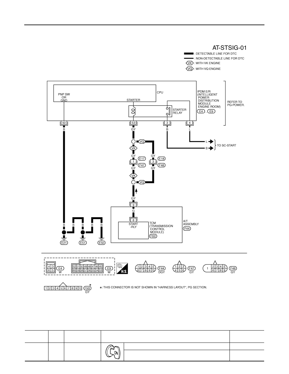
Wiring Diagram - AT - STSIG
INFOID:0000000001327176
TCM terminals and data are reference value. Measured between each terminal and ground.
TCWM0247E
Terminal
Wire
color
Item
Condition
Data (Approx.)
9
GY
Starter relay
Selector lever in “N” and “P” positions.
Battery voltage
Selector lever in other positions.
0 V
DTC P0615 START SIGNAL CIRCUIT
AT-99
< SERVICE INFORMATION >
D
E
F
G
H
I
J
K
L
M
A
B
AT
N
O
P
Diagnosis Procedure
INFOID:0000000001327177
1.
CHECK STARTER RELAY
With CONSULT-III
1.
Turn ignition switch ON.
2.
Select “SELECTION FROM MENU” in “DATA MONITOR” mode for “TRANSMISSION” with CONSULT-III
and check monitor “STARTER RELAY” ON/OFF.
Without CONSULT-III
1.
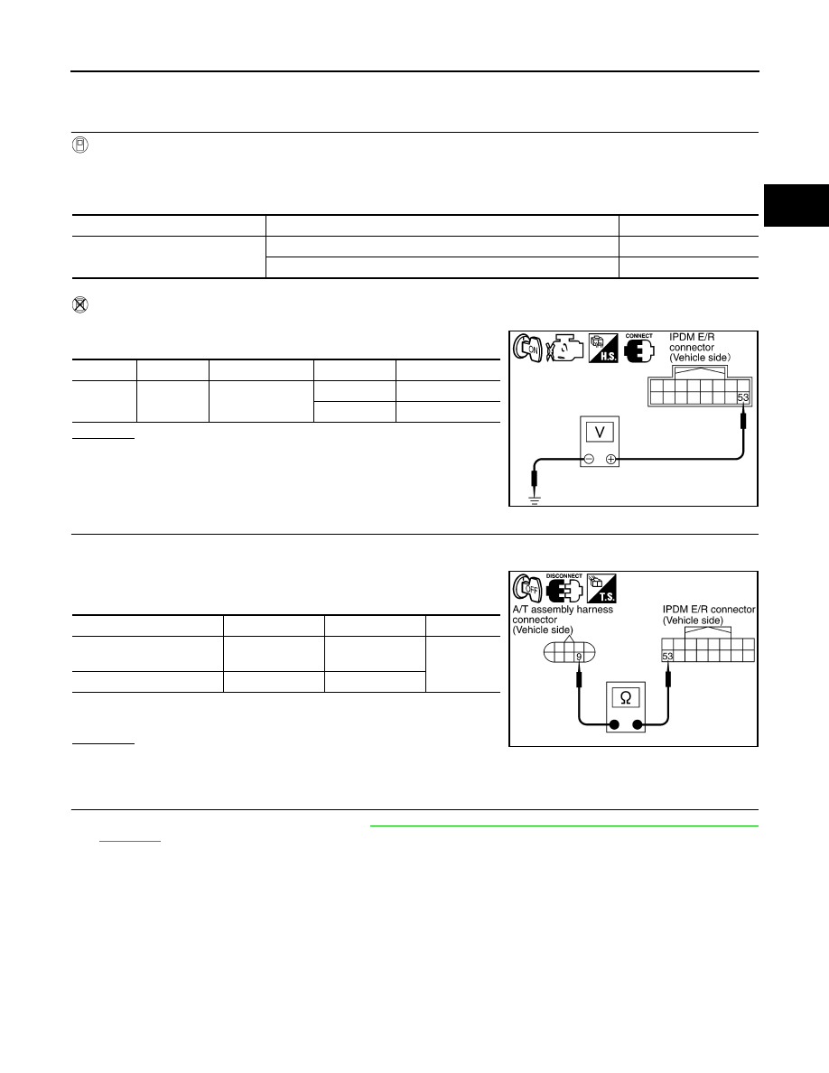
Turn ignition switch ON.
2.
Check voltage between the IPDM E/R connector and ground.
OK or NG
OK
>> GO TO 5.
NG
>> GO TO 2.
2.
CHECK HARNESS BETWEEN A/T ASSEMBLY HARNESS CONNECTOR AND IPDM E/R CONNECTOR
1.
Turn ignition switch OFF.
2.
Disconnect A/T assembly harness connector and IPDM E/R connector.
3.
Check continuity between A/T assembly harness connector and
IPDM E/R connector.
4.
If OK, check harness for short to ground and short to power.
5.
Reinstall any part removed.
OK or NG
OK
>> GO TO 3.
NG
>> Repair open circuit or short to ground or short to power in harness or connectors.
3.
CHECK TERMINAL CORD ASSEMBLY
1.
Remove control valve with TCM. Refer to
AT-215, "Control Valve with TCM and A/T Fluid Temperature
.
2.
Disconnect A/T assembly harness connector and TCM connector.
Item name
Condition
Display value
STARTER RELAY
Selector lever in “N” and “P” positions.
ON
Selector lever in other positions.
OFF
Name
Connector
Terminal
Shift position
Voltage (Approx.)
Starter re-
lay
E9
53 - Ground
“N” and “P”
Battery voltage
“R” and “D”
0 V
SCIA2103E
Item
Connector
Terminal
Continuity
A/T assembly harness con-
nector
F44
9
Yes
IPDM E/R connector
E9
53
SCIA5439E
Нет комментариевНе стесняйтесь поделиться с нами вашим ценным мнением.
Текст