Infiniti FX35 / FX45. Manual — part 41
AT-92
< SERVICE INFORMATION >
TROUBLE DIAGNOSIS
1.
CHECK A/T CHECK INDICATOR LAMP
1.
Start the engine with selector lever in “P” position. Warm engine to normal operating temperature.
2.
Turn ignition switch ON and OFF at least twice, then leave it in the OFF position.
3.
Wait 10 seconds.
4.
Turn ignition switch ON. (Do not start engine.)
Does A/T CHECK indicator lamp come on for about 2 seconds?
YES
>> GO TO 2.
NO
>> Go to
AT-170, "A/T Check Indicator Lamp Does Not Come On"
.
2.
JUDGEMENT PROCEDURE
1.
Turn ignition switch OFF.
2.
Keep pressing shift lock release button.
3.
Move selector lever from “P” to “D” position.
4.
Release accelerator pedal. (Set the closed throttle position signal ON.)
5.
Depress brake pedal. (Stop lamp switch signal ON.)
6.
Turn ignition switch ON. (Do not start engine.)
7.
Wait 3 seconds.
8.
Move the selector lever to the manual shift gate side. (Manual mode signal ON.)
9.
Release brake pedal. (Stop lamp switch signal OFF.)
10. Move the selector lever to “D” position. (Manual mode signal OFF.)
11. Depress brake pedal. (Stop lamp switch signal ON.)
12. Release brake pedal. (Stop lamp switch signal OFF.)
13. Depress accelerator pedal fully and release it.
>> GO TO 3.
3.
CHECK SELF-DIAGNOSIS CODE
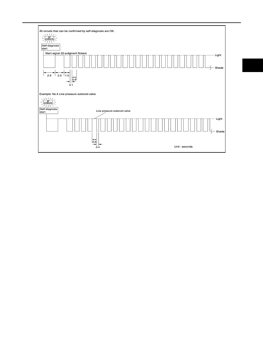
Check A/T CHECK indicator lamp. Refer to "Judgement Self-diagnosis Code".
If the system does not go into self-diagnostics. Refer to
>> DIAGNOSIS END
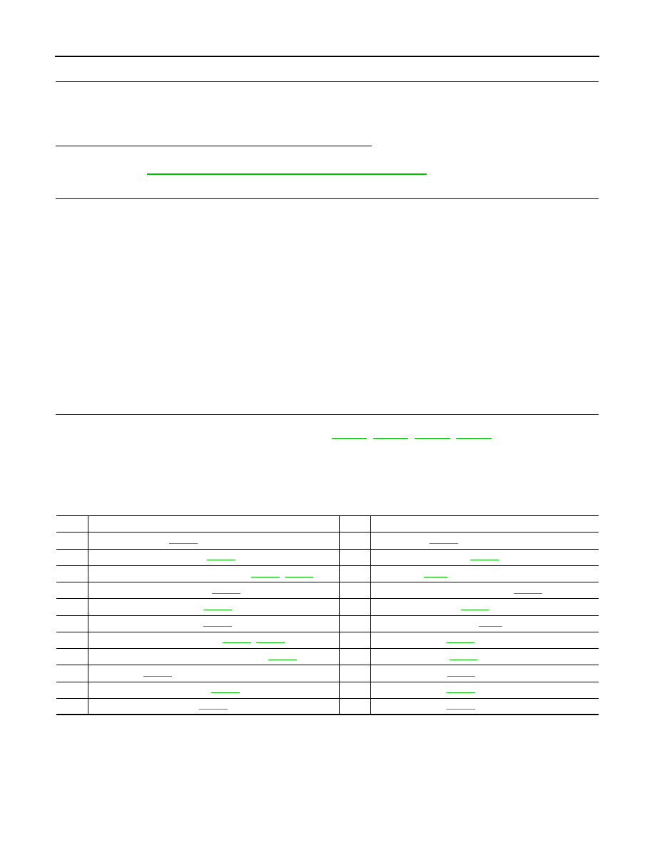
Judgement Self-diagnosis Code
If there is a malfunction, the lamp lights up for the time corresponding to the suspect circuit.
No.
Malfunctioning item
No.
Malfunctioning item
1
Revolution sensor
12
2
Direct clutch solenoid valve
13
A/T 1st engine braking
3
Torque converter clutch solenoid valve
14
4
Line pressure solenoid valve
15
Accelerator pedal position sensor
5
Input clutch solenoid valve
16
6
Front brake solenoid valve
17
CAN communication line
7
Low coast brake solenoid valve
18
1st gear function
8
High and low reverse clutch solenoid valve
19
2nd gear function
9
PNP switch
20
3rd gear function
10
A/T fluid temperature sensor
21
11
Turbine revolution sensor
22
TROUBLE DIAGNOSIS
AT-93
< SERVICE INFORMATION >
D
E
F
G
H
I
J
K
L
M
A
B
AT
N
O
P
Erase Self-diagnosis
• In order to make it easier to find the cause of hard-to-duplicate malfunctions, malfunction information is
stored into the control unit as necessary during use by the user. This memory is not erased no matter how
many times the ignition switch is turned ON and OFF.
• However, this information is erased by turning ignition switch “OFF” after performing self-diagnostics or by
erasing the memory using the CONSULT-III.
SCIA8153E

AT-94
< SERVICE INFORMATION >
DTC U1000 CAN COMMUNICATION LINE
DTC U1000 CAN COMMUNICATION LINE
Description
INFOID:0000000001327165
CAN (Controller Area Network) is a serial communication line for real time application. It is an on-vehicle mul-
tiplex communication line with high data communication speed and excellent malfunction detection ability.
Many electronic control units are equipped onto a vehicle, and each control unit shares information and links
with other control units during operation (not independent). In CAN communication, control units are con-
nected with 2 communication lines (CAN-H line, CAN-L line) allowing a high rate of information transmission
with less wiring. Each control unit transmits/receives data but selectively reads required data only.
On Board Diagnosis Logic
INFOID:0000000001327166
Diagnostic trouble code “U1000 CAN COMM CIRCUIT” with CONSULT-III or 17th judgement flicker without
CONSULT-III is detected when TCM cannot communicate to other control units.
Possible Cause
INFOID:0000000001327167
Harness or connectors
(CAN communication line is open or shorted.)
DTC Confirmation Procedure
INFOID:0000000001327168
NOTE:
If “DTC Confirmation Procedure” has been previously performed, always turn ignition switch OFF and
wait at least 10 seconds before performing the next test.
After the repair, perform the following procedure to confirm the malfunction is eliminated.
WITH CONSULT-III
1.
Turn ignition switch ON.
2.
Select “ECU INPUT SIGNALS” or “MAIN SIGNALS” in “DATA MONITOR” mode for “TRANSMISSION”
with CONSULT-III.
3.
Start engine and wait for at least 6 seconds.
4.
If DTC is detected, go to
WITH GST
Follow the procedure “WITH CONSULT-III”.
DTC U1000 CAN COMMUNICATION LINE
AT-95
< SERVICE INFORMATION >
D
E
F
G
H
I
J
K
L
M
A
B
AT
N
O
P
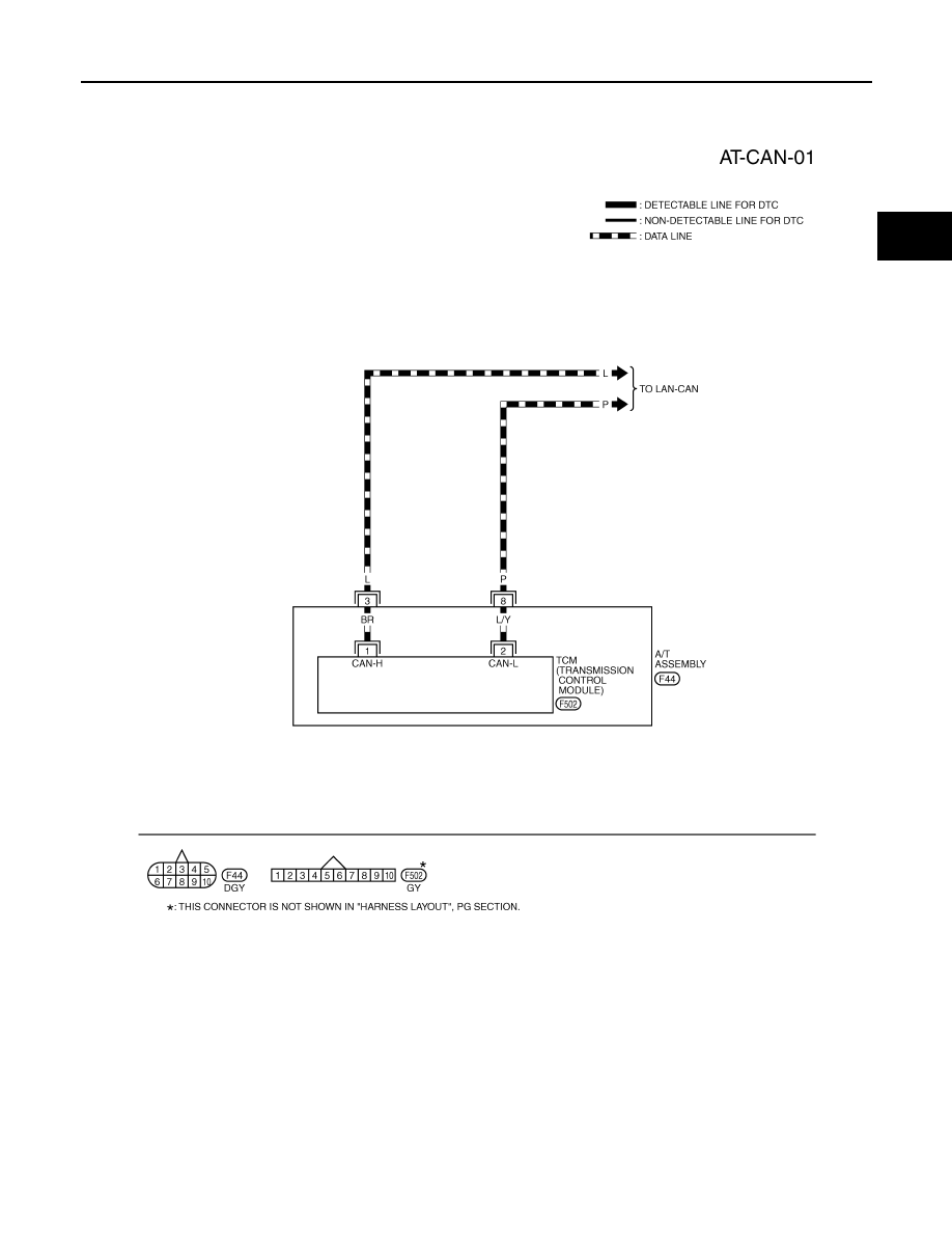
Wiring Diagram - AT - CAN
INFOID:0000000001327169
TCWM0496E
Нет комментариевНе стесняйтесь поделиться с нами вашим ценным мнением.
Текст