Infiniti FX35 / FX45. Manual — part 795
FRONT FOG LAMP
LT-75
< SERVICE INFORMATION >
C
D
E
F
G
H
I
J
L
M
A
B
LT
N
O
P
3.
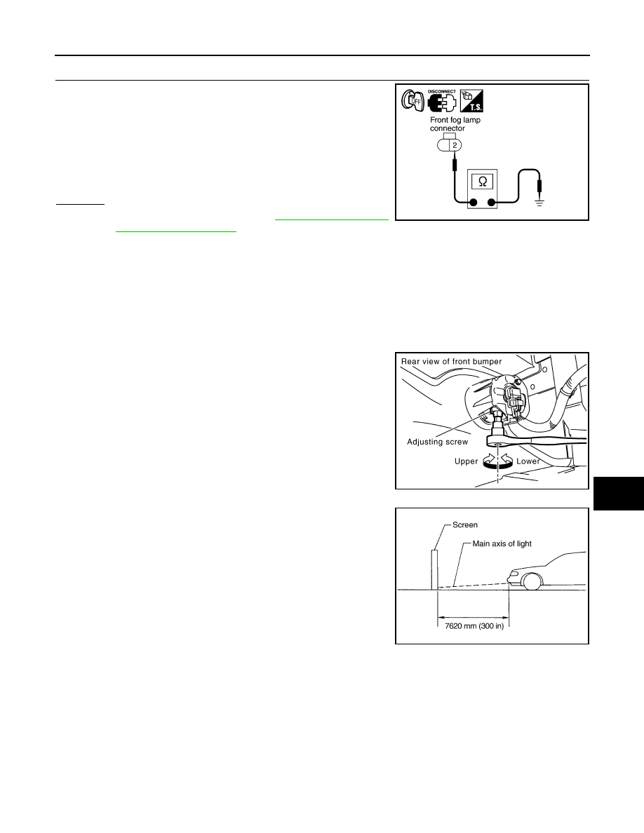
CHECK FRONT FOG LAMP GROUND
1.
Check continuity between front fog lamp RH harness connector
E102 terminal 2 and ground.
2.
Check continuity between front fog lamp LH harness connector
E45 terminal 2 and ground.
OK or NG
OK
>> Replace IPDM E/R. Refer to
.
NG
>> Repair harness or connector.
Aiming Adjustment
INFOID:0000000001328340
Front fog lamp is a semi-sealed beam type which uses a replaceable halogen bulb. Before performing aiming
adjustment, make sure of the following.
• Keep all tires inflated to correct pressure.
• Place vehicle on level ground.
• See that vehicle is unloaded (except for full levels of coolant, engine oil and fuel, and spare tire, jack, and
tools). Have the driver or equivalent weight placed in driver seat.
Adjust aiming in the vertical direction by turning adjusting screw.
1.
Set the distance between the screen and the center of front fog
lamp lens as shown at left.
2.
Turn front fog lamps ON.
2 – Ground
: Continuity should exist.
2 – Ground
: Continuity should exist.
PKIA6277E
PKIC9713E
PKIB1672E
LT-76
< SERVICE INFORMATION >
FRONT FOG LAMP
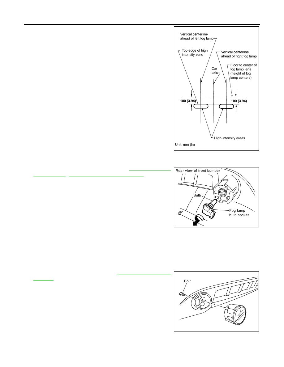
3.
Adjust front fog lamps using adjusting screw so that the top edge
of the high intensity zone is 100 mm (3.94 in) below the height of
front fog lamp centers as shown at left.
• When performing adjustment, if necessary, cover headlamps
and opposite front fog lamp.
Bulb Replacement
INFOID:0000000001328341
1.
Remove fender protector (front). Refer to
EI-14, "Component Parts Location"
.
2.
Disconnect front fog lamp connector.
3.
Turn bulb socket counterclockwise and unlock it.
CAUTION:
• Never touch the glass of bulb directly by hand. Keep
grease and other oily matters away from it. Never touch
bulb by hand while it is lit or right after being turned off.
Burning may result.
• Never leave bulb out of front fog lamp reflector for a long time because dust, moisture smoke,
etc. May affect the performance of front fog lamp. When replacing bulb, be sure to replace it with
new one.
Removal and Installation
INFOID:0000000001328342
REMOVAL
1.
Remove front bumper fascia. Refer to
2.
Remove front fog lamp mounting bolt.
3.
Pull out front fog lamp from vehicle and disconnect front fog
lamp connector.
INSTALLATION
Installation is the reverse order of removal.
PKIB1673E
Front fog lamp
: 12 V - 35 W (H8)
PKIC9689E
PKIC9690E

FRONT FOG LAMP
LT-77
< SERVICE INFORMATION >
C
D
E
F
G
H
I
J
L
M
A
B
LT
N
O
P
Front fog lamp mounting bolt
: 5.5 N·m (0.55 kg-m, 49 in-lb)
LT-78
< SERVICE INFORMATION >
TURN SIGNAL AND HAZARD WARNING LAMPS
TURN SIGNAL AND HAZARD WARNING LAMPS
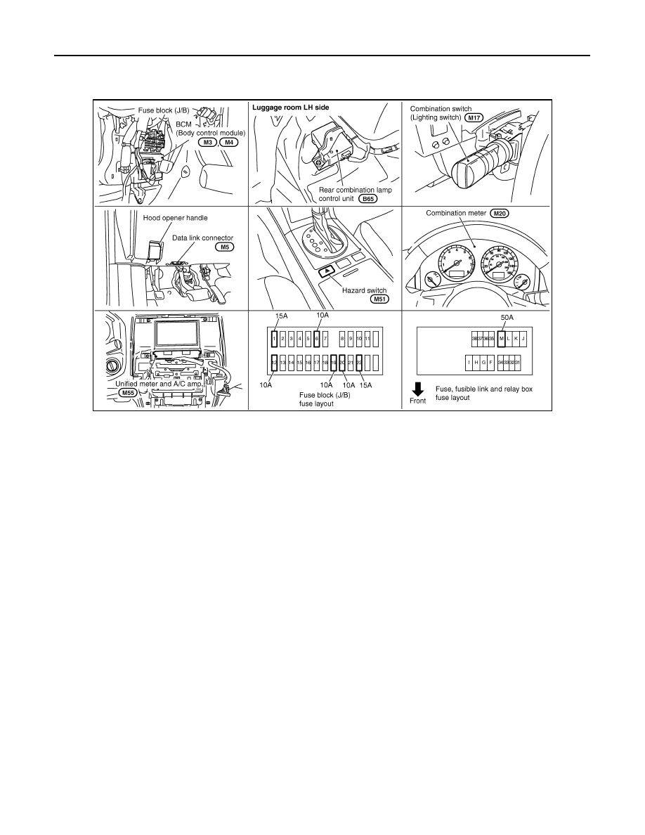
Component Parts and Harness Connector Location
INFOID:0000000001328343
System Description
INFOID:0000000001328344
OUTLINE
Power is supplied at all times
• through 50A fusible link (letter M, located in fuse and fusible link block)
• to BCM terminal 55,
• through 15A fuse [No. 22, located in fuse block (J/B)]
• to BCM terminal 42,
• through 10A fuse [No. 19, located in fuse block (J/B)]
• to combination meter terminal 8.
• through 10A fuse [No. 20, located in fuse block (J/B)]
• to rear combination lamp control unit terminal 1.
When ignition switch is in ON or START position, power is supplied
• through 15A fuse [No. 1, located in fuse block (J/B)]
• to BCM (body control module) terminal 38,
• through 10A fuse [No. 14, located in fuse block (J/B)]
• to combination meter terminal 7.
When ignition switch is in ACC or ON position, power is supplied
• through 10A fuse [No. 6, located in fuse block (J/B)]
• to BCM terminal 11.
Ground is supplied
• to rear combination lamp control unit terminal 7
• through grounds E21, E50 and E51,
• to BCM terminals 49 and 52, and
• to combination meter terminals 5, 6 and 15
• through grounds M35, M45 and M85.
TURN SIGNAL OPERATION
LH Turn Signal Lamp
PKIC9692E
Нет комментариевНе стесняйтесь поделиться с нами вашим ценным мнением.
Текст