Infiniti FX35 / FX45. Manual — part 793
FRONT FOG LAMP
LT-67
< SERVICE INFORMATION >
C
D
E
F
G
H
I
J
L
M
A
B
LT
N
O
P
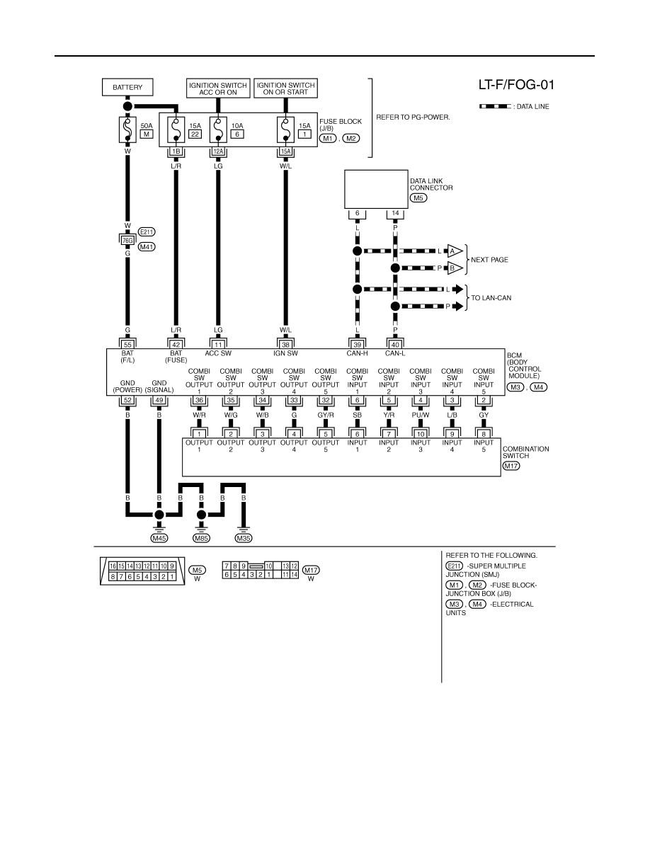
• to BCM terminals 49 and 52
• through grounds M35, M45 and M85,
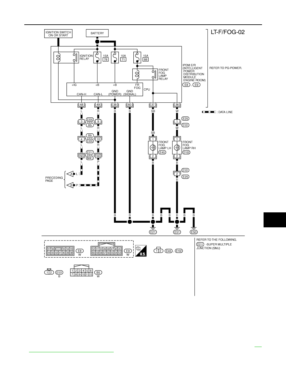
• to IPDM E/R terminals 38 and 60
• through grounds E21, E50 and E51.
FRONT FOG LAMP OPERATION
The front fog lamp switch is built into combination switch. The lighting switch must be in the 2ND position or
AUTO position (headlamp is ON) and the front fog lamp switch must be ON for front fog lamp operation.
With the front fog lamp switch in the ON position, the CPU located in the IPDM E/R grounds the coil side of the
front fog lamp relay. The front fog lamp relay then directs power
• through IPDM E/R terminal 36
• to front fog lamp RH terminal 1,
• through IPDM E/R terminal 37
• to front fog lamp LH terminal 1.
Ground is supplied
• to front fog lamp RH and LH terminals 2
• through grounds E21, E50 and E51.
With power and grounds supplied, front fog lamps illuminate.
COMBINATION SWITCH READING FUNCTION
EXTERIOR LAMP BATTERY SAVER CONTROL
When the combination switch (lighting switch) is in the 2ND position (ON), the front fog lamp switch is ON, and
the ignition switch is turned from ON or ACC to OFF, the battery saver control feature is activated.
Under this condition, the front fog lamps (and headlamps) remain illuminated for 5 minutes, then the front fog
lamps (and headlamps) are turned off.
Exterior lamp battery saver control mode can be changed by the function setting of CONSULT-III.
CAN Communication System Description
INFOID:0000000001328329
CAN (Controller Area Network) is a serial communication line for real time application. It is an on-vehicle mul-
tiplex communication line with high data communication speed and excellent error detection ability. Many elec-
tronic control units are equipped onto a vehicle, and each control unit shares information and links with other
control units during operation (not independent). In CAN communication, control units are connected with 2
communication lines (CAN H line, CAN L line) allowing a high rate of information transmission with less wiring.
Each control unit transmits/receives data but selectively reads required data only.
CAN Communication Unit
INFOID:0000000001328330
LT-68
< SERVICE INFORMATION >
FRONT FOG LAMP
Wiring Diagram - F/FOG -
INFOID:0000000001328331
TKWM4303E
FRONT FOG LAMP
LT-69
< SERVICE INFORMATION >
C
D
E
F
G
H
I
J
L
M
A
B
LT
N
O
P
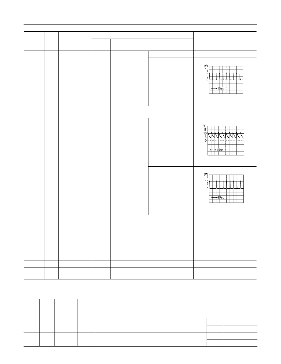
Terminal and Reference Value for BCM
INFOID:0000000001328332
CAUTION:
• Check combination switch system terminal waveform under the loaded condition with lighting
switch, turn signal switch and wiper switch OFF not to be fluctuated by overloaded.
• Turn wiper intermittent dial position to 4 except when checking waveform or voltage of wiper inter-
mittent dial position. Wiper intermittent dial position can be confirmed on CONSULT-III. Refer to
103, "CONSULT-III Functions (BCM)"
TKWM4304E
LT-70
< SERVICE INFORMATION >
FRONT FOG LAMP
Terminal and Reference Value for IPDM E/R
INFOID:0000000001328333
Terminal
No.
Wire
color
Signal name
Measuring condition
Reference value
Ignition
switch
Operation or condition
3
L/B
Combination
switch input 4
ON
Lighting, turn, wiper
switch
(Wiper intermittent
dial position 4)
OFF
Approx. 0 V
Front fog lamp switch
(Operates only front fog
lamp switch)
Approx. 0.8 V
11
LG
Ignition switch
(ACC)
ACC
—
Battery voltage
32
GY/R
Combination
switch output 5
ON
Lighting, turn, wiper
switch
(Wiper intermittent
dial position 4)
OFF
Approx. 7.2 V
Front fog lamp switch
(Operates only front fog
lamp switch)
Approx. 1.0 V
38
W/L
Ignition switch
(ON)
ON
—
Battery voltage
39
L
CAN
−
H
—
—
—
40
P
CAN
−
L
—
—
—
42
L/R
Battery power
supply
OFF
—
Battery voltage
49
B
Ground
ON
—
Approx. 0 V
52
B
Ground
ON
—
Approx. 0 V
55
G
Battery power
supply
OFF
—
Battery voltage
PKIB4955J
PKIB4960J
PKIB4956J
Termi-
nal
No.
Wire
color
Signal
name
Measuring condition
Reference value
Ignition
switch
Operation or condition
36
W
Front fog
lamp (RH)
ON
Lighting switch must be in the 2ND position or AUTO position
(headlamp is ON) and front fog lamp switch must be ON.
OFF
Approx. 0 V
ON
Battery voltage
37
SB
Front fog
lamp (LH)
ON
Lighting switch must be in the 2ND position or AUTO position
(headlamp is ON) and front fog lamp switch must be ON.
OFF
Approx. 0 V
ON
Battery voltage
Нет комментариевНе стесняйтесь поделиться с нами вашим ценным мнением.
Текст