Infiniti FX35 / FX45. Manual — part 362

DTC P0127 IAT SENSOR
EC-209
< SERVICE INFORMATION >
[VQ35DE]
C
D
E
F
G
H
I
J
K
L
M
A
EC
N
P
O
Removal and Installation
INFOID:0000000001326039
MASS AIR FLOW SENSOR
SEF012P

EC-210
< SERVICE INFORMATION >
[VQ35DE]
DTC P0128 THERMOSTAT FUNCTION
DTC P0128 THERMOSTAT FUNCTION
On Board Diagnosis Logic
INFOID:0000000001326040
Engine coolant temperature has not risen enough to open the thermostat even though the engine has run long
enough.
This is due to a leak in the seal or the thermostat stuck open.
DTC Confirmation Procedure
INFOID:0000000001612840
NOTE:
If DTC Confirmation Procedure has been previously conducted, always turn ignition switch OFF and wait at
least 10 seconds before conducting the next test.
TESTING CONDITION:
• For best results, perform at ambient temperature of –10
°
C (14
°
F) or higher.
• For best results, perform at engine coolant temperature of –10
°
C (14
°
F) to 71
°
C (160
°
F).
• Before performing the following procedure, do not fill with the fuel.
WITH CONSULT-III
1.
Turn A/C switch OFF.
2.
Turn blower fan switch OFF.
3.
Turn ignition switch ON.
4.
Select “COOLAN TEMP/S” in “DATA MONITOR” mode with CONSULT-III.
5.
Check the indication of “COOLAN TEMP/S”.
If it is below 71
°
C (160
°
F), go to following step.
If it is above 71
°
C (160
°
F), cool down the engine to less than 71
°
C (160
°
F), then go to next step.
6.
Start engine.
7.
Wait at idle for a least 30 minutes.
If “COOLAN TEMP/S” increases to more than 71
°
C (160
°
F) within 30 minutes, turn ignition switch
OFF because the test result will be OK.
8.
Check 1st trip DTC.
9.
If 1st trip DTC is detected, go to
WITH GST
Follow the procedure “WITH CONSULT-III” above.
Diagnosis Procedure
INFOID:0000000001612841
1.
CHECK ENGINE COOLANT TEMPERATURE SENSOR
EC-211, "Component Inspection"
.
OK or NG
OK
>> GO TO 2.
NG
>> Replace engine coolant temperature sensor.
2.
CHECK THERMOSTAT
CO-27, "Removal and Installation"
.
OK or NG
OK
>> INSPECTION END
NG
>> Replace thermostat.
DTC No.
Trouble diagnosis name
DTC detecting condition
Possible cause
P0128
0128
Thermostat function
The engine coolant temperature does not reach
to specified temperature even though the en-
gine has run long enough.
• Thermostat
• Leakage from sealing portion of thermo-
stat
• Engine coolant temperature sensor
DTC P0128 THERMOSTAT FUNCTION
EC-211
< SERVICE INFORMATION >
[VQ35DE]
C
D
E
F
G
H
I
J
K
L
M
A
EC
N
P
O
Component Inspection
INFOID:0000000001326043
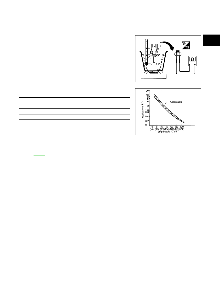
ENGINE COOLANT TEMPERATURE SENSOR
Check resistance between engine coolant temperature sensor termi-
nals 1 and 2 as shown in the figure.
<Reference data>
If NG, replace engine coolant temperature sensor.
Removal and Installation
INFOID:0000000001326044
ENGINE COOLANT TEMPERATURE SENSOR
PBIB2005E
Engine coolant temperature
°
C (
°
F)
Resistance
k
Ω
20 (68)
2.1 - 2.9
50 (122)
0.68 - 1.00
90 (194)
0.236 - 0.260
SEF012P
EC-212
< SERVICE INFORMATION >
[VQ35DE]
DTC P0130, P0150 A/F SENSOR 1
DTC P0130, P0150 A/F SENSOR 1
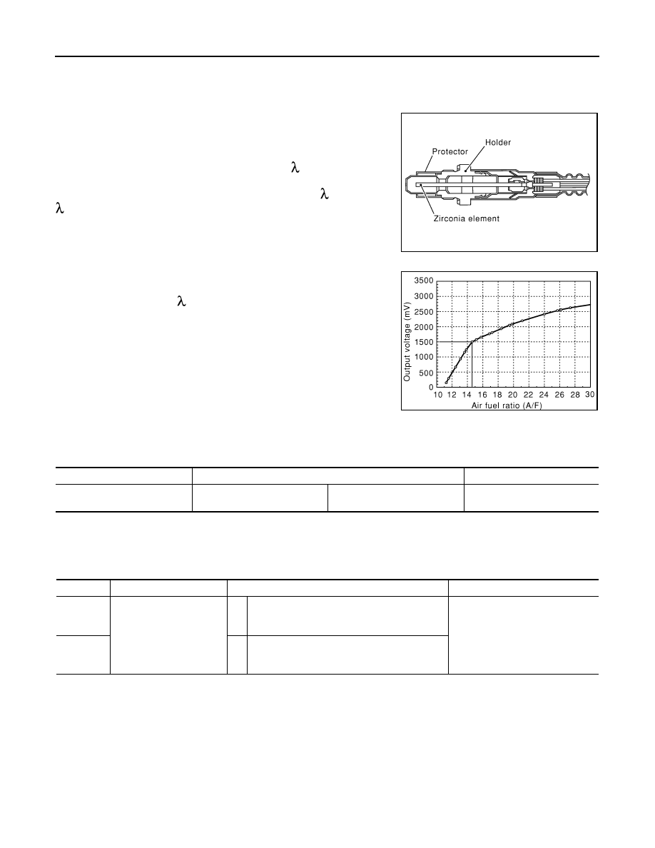
Component Description
INFOID:0000000001326045
The air fuel ratio (A/F) sensor is a planar dual-cell limit current sen-
sor. The sensor element of the air fuel ratio (A/F) sensor is the com-
bination of a Nernst concentration cell (sensor cell) with an oxygen-
pump cell, which transports ions. It has a heater in the element.
The sensor is capable of precise measurement = 1, but also in the
lean and rich range. Together with its control electronics, the sensor
outputs a clear, continuous signal throughout a wide range (0.7 <
< air).
The exhaust gas components diffuse through the diffusion gap at the
electrode of the oxygen pump and Nernst concentration cell, where
they are brought to thermodynamic balance.
An electronic circuit controls the pump current through the oxygen-
pump cell so that the composition of the exhaust gas in the diffusion
gap remains constant at = 1. Therefore, the air fuel ratio (A/F) sen-
sor is able to indicate air/fuel ratio by this pumping of current. In
addition, a heater is integrated in the sensor to ensure the required
operating temperature of 700 - 800
°
C (1,292 - 1,472
°
F).
CONSULT-III Reference Value in Data Monitor Mode
INFOID:0000000001326046
Specification data are reference values.
On Board Diagnosis Logic
INFOID:0000000001326047
To judge the malfunction, the diagnosis checks that the A/F signal computed by ECM from the air fuel ratio (A/
F) sensor 1 signal fluctuates according to fuel feedback control.
DTC Confirmation Procedure
INFOID:0000000001326048
Perform PROCEDURE FOR MALFUNCTION A first.
If the DTC cannot be confirmed, perform PROCEDURE FOR MALFUNCTION B.
NOTE:
If DTC Confirmation Procedure has been previously conducted, always turn ignition switch OFF and wait at
least 10 seconds before conducting the next test.
TESTING CONDITION:
Before performing the following procedure, confirm that battery voltage is more than 11V at idle.
PROCEDURE FOR MALFUNCTION A
SEF579Z
SEF580Z
MONITOR ITEM
CONDITION
SPECIFICATION
A/F SEN1 (B1)
A/F SEN1 (B2)
• Engine: After warming up
Maintaining engine speed at
2,000 rpm
Fluctuates around 1.5V
DTC No.
Trouble diagnosis name
DTC detecting condition
Possible Cause
P0130
0130
(Bank 1)
Air fuel ratio (A/F) sensor 1
circuit
A)
The A/F signal computed by ECM from the A/F
sensor 1 signal is constantly in the range other
than approx. 1.5V.
• Harness or connectors
(The A/F sensor 1 circuit is open
or shorted.)
• Air fuel ratio (A/F) sensor 1
P0150
0150
(Bank 2)
B)
The A/F signal computed by ECM from the A/F
sensor 1 signal is constantly approx. 1.5V.
Нет комментариевНе стесняйтесь поделиться с нами вашим ценным мнением.
Текст