Infiniti FX35 / FX45. Manual — part 360
DTC P0122, P0123 TP SENSOR
EC-201
< SERVICE INFORMATION >
[VQ35DE]
C
D
E
F
G
H
I
J
K
L
M
A
EC
N
P
O
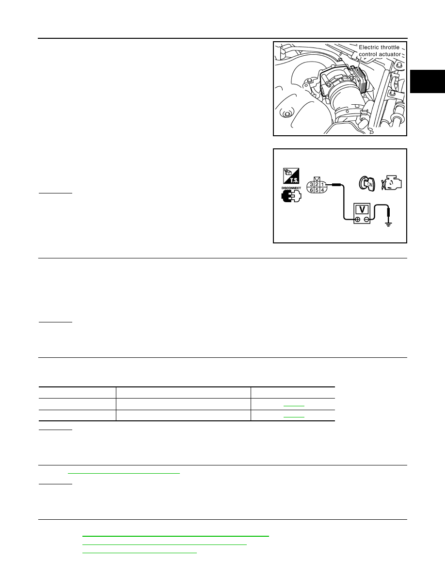
1.
Disconnect electric throttle control actuator harness connector.
2.
Turn ignition switch ON.
3.
Check voltage between electric throttle control actuator terminal
1 and ground with CONSULT-III or tester.
OK or NG
OK
>> GO TO 7.
NG
>> GO TO 3.
3.
CHECK THROTTLE POSITION SENSOR 2 POWER SUPPLY CIRCUIT-II
1.
Turn ignition switch OFF.
2.
Disconnect ECM harness connector.
3.
Check harness continuity between electric throttle control actuator terminal 1 and ECM terminal 47.
Refer to Wiring Diagram.
OK or NG
OK
>> GO TO 4.
NG
>> Repair open circuit.
4.
CHECK THROTTLE POSITION SENSOR 2 POWER SUPPLY CIRCUIT-III
Check the following.
• Harness for short to power and short to ground, between the following terminals.
OK or NG
OK
>> GO TO 5.
NG
>> Repair short to ground or short to power in harness or connectors.
5.
CHECK APP SENSOR
EC-517, "Component Inspection"
OK or NG
OK
>> GO TO 11.
NG
>> GO TO 6.
6.
REPLACE ACCELERATOR PEDAL ASSEMBLY
1.
Replace accelerator pedal assembly.
2.
EC-85, "Accelerator Pedal Released Position Learning"
3.
EC-85, "Throttle Valve Closed Position Learning"
.
4.
EC-85, "Idle Air Volume Learning"
PBIB1557E
Voltage: Approximately 5V
PBIB0082E
Continuity should exist.
ECM terminal
Sensor terminal
Reference Wiring Diagram
47
Electric throttle control actuator terminal 1
91
APP sensor terminal 4

EC-202
< SERVICE INFORMATION >
[VQ35DE]
DTC P0122, P0123 TP SENSOR
>> INSPECTION END
7.
CHECK THROTTLE POSITION SENSOR 2 GROUND CIRCUIT FOR OPEN AND SHORT
1.
Turn ignition switch OFF.
2.
Disconnect ECM harness connector.
3.
Check harness continuity between electric throttle control actuator terminal 5 and ECM terminal 66.
Refer to Wiring Diagram.
4.
Also check harness for short to ground and short to power.
OK or NG
OK
>> GO TO 8.
NG
>> Repair open circuit or short to ground or short to power in harness or connectors.
8.
CHECK THROTTLE POSITION SENSOR 2 INPUT SIGNAL CIRCUIT FOR OPEN AND SHORT
1.
Check harness continuity between ECM terminal 69 and electric throttle control actuator terminal 2.
Refer to Wiring Diagram.
2.
Also check harness for short to ground and short to power.
OK or NG
OK
>> GO TO 9.
NG
>> Repair open circuit or short to ground or short to power in harness or connectors.
9.
CHECK THROTTLE POSITION SENSOR
EC-202, "Component Inspection"
OK or NG
OK
>> GO TO 11.
NG
>> GO TO 10.
10.
REPLACE ELECTRIC THROTTLE CONTROL ACTUATOR
1.
Replace the electric throttle control actuator.
2.
EC-85, "Throttle Valve Closed Position Learning"
.
3.
EC-85, "Idle Air Volume Learning"
>> INSPECTION END
11.
CHECK INTERMITTENT INCIDENT
>> INSPECTION END
Component Inspection
INFOID:0000000001326026
THROTTLE POSITION SENSOR
1.
Reconnect all harness connectors disconnected.
2.
EC-85, "Throttle Valve Closed Position Learning"
.
3.
Turn ignition switch ON.
4.
Set selector lever to D position.
Continuity should exist.
Continuity should exist.
DTC P0122, P0123 TP SENSOR
EC-203
< SERVICE INFORMATION >
[VQ35DE]
C
D
E
F
G
H
I
J
K
L
M
A
EC
N
P
O
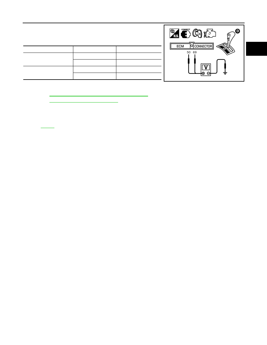
5.
Check voltage between ECM terminals 50 (TP sensor 1signal),
69 (TP sensor 2signal) and body ground under the following
conditions.
6.
If NG, replace electric throttle control actuator and go to the next
step.
7.
EC-85, "Throttle Valve Closed Position Learning"
.
8.
EC-85, "Idle Air Volume Learning"
Removal and Installation
INFOID:0000000001326027
ELECTRIC THROTTLE CONTROL ACTUATOR
Terminal
Accelerator pedal
Voltage
50
(Throttle position sensor 1)
Fully released
More than 0.36V
Fully depressed
Less than 4.75V
69
(Throttle position sensor 2)
Fully released
Less than 4.75V
Fully depressed
More than 0.36V
PBIB1608E
EC-204
< SERVICE INFORMATION >
[VQ35DE]
DTC P0125 ECT SENSOR
DTC P0125 ECT SENSOR
Component Description
INFOID:0000000001326028
NOTE:
If DTC P0125 is displayed with P0117 or P0118, first perform the trouble diagnosis for DTC P0117 or
P0118. Refer to
.
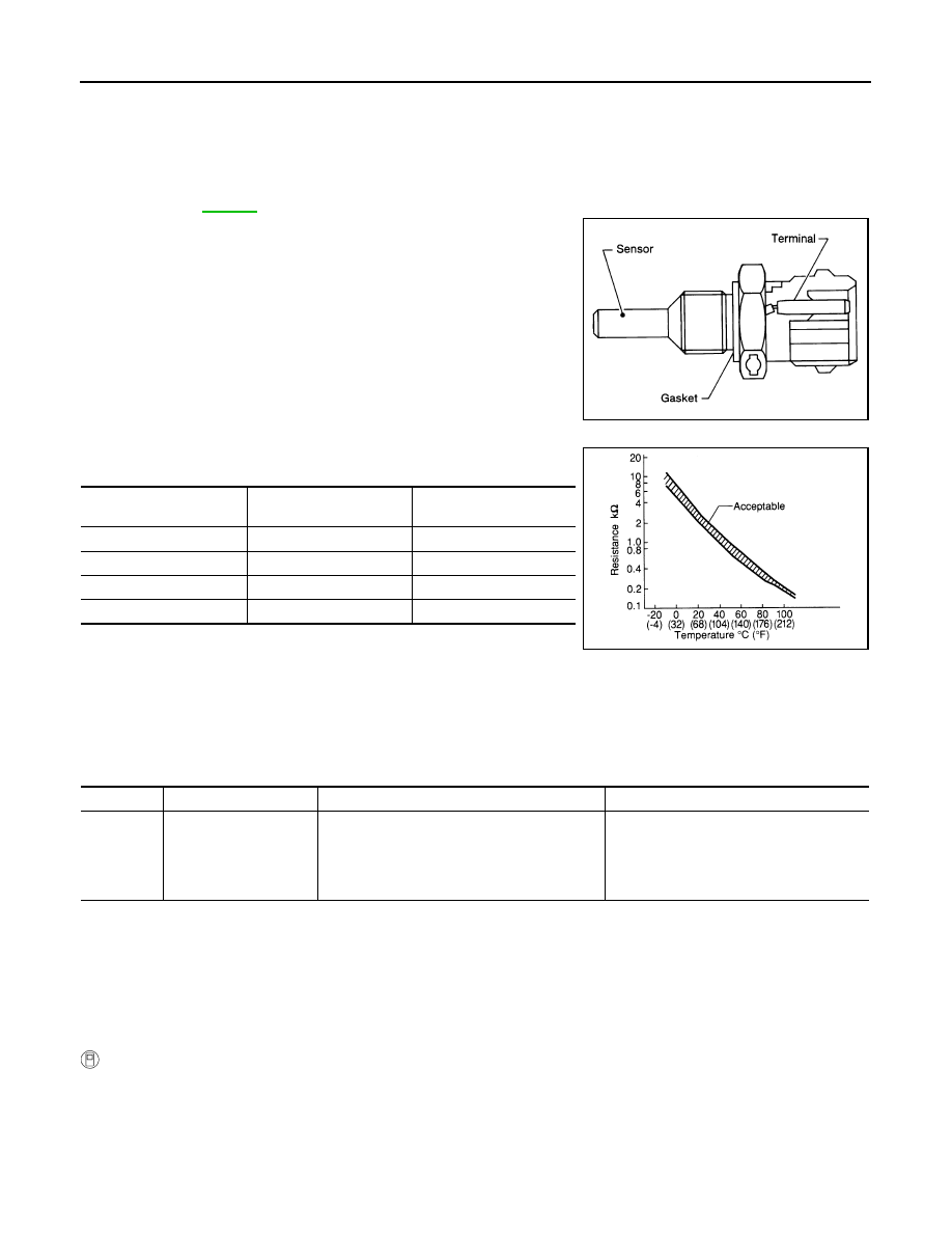
The engine coolant temperature (ECT) sensor is used to detect the
engine coolant temperature. The sensor modifies a voltage signal
from the ECM. The modified signal returns to the ECM as the engine
coolant temperature input. The sensor uses a thermistor which is
sensitive to the change in temperature. The electrical resistance of
the thermistor decreases as temperature increases.
<Reference data>
*: This data is reference values and is measured between ECM terminal 73 (Engine
coolant temperature sensor) and ground.
CAUTION:
Do not use ECM ground terminals when measuring input/output voltage. Doing so may result in dam-
age to the ECM's transistor. Use a ground other than ECM terminals, such as the ground.
On Board Diagnosis Logic
INFOID:0000000001326029
DTC Confirmation Procedure
INFOID:0000000001326030
CAUTION:
Be careful not to overheat engine.
NOTE:
If DTC Confirmation Procedure has been previously conducted, always turn ignition switch OFF and wait at
least 10 seconds before conducting the next test.
WITH CONSULT-III
1.
Turn ignition switch ON.
2.
Select “DATA MONITOR” mode with CONSULT-III.
3.
Check that “COOLAN TEMP/S” is above 10
°
C (50
°
F).
If it is above 10
°
C (50
°
F), the test result will be OK.
If it is below 10
°
C (50
°
F), go to following step.
4.
Start engine and run it for 65 minutes at idle speed.
SEF594K
Engine coolant
temperature
°
C (
°
F)
Voltage*
V
Resistance
k
Ω
-10 (14)
4.4
7.0 - 11.4s
20 (68)
3.5
2.1 - 2.9
50 (122)
2.2
0.68 - 1.00
90 (194)
0.9
0.236 - 0.260
SEF012P
DTC No.
Trouble diagnosis name
DTC detecting condition
Possible cause
P0125
0125
Insufficient engine cool-
ant temperature for
closed loop fuel control
• Voltage sent to ECM from the sensor is not
practical, even when some time has passed
after starting the engine.
• Engine coolant temperature is insufficient for
closed loop fuel control.
• Harness or connectors
(High resistance in the circuit)
• Engine coolant temperature sensor
• Thermostat
Нет комментариевНе стесняйтесь поделиться с нами вашим ценным мнением.
Текст