Infiniti FX35 / FX45. Manual — part 374
DTC P0138, P0158 HO2S2
EC-257
< SERVICE INFORMATION >
[VQ35DE]
C
D
E
F
G
H
I
J
K
L
M
A
EC
N
P
O
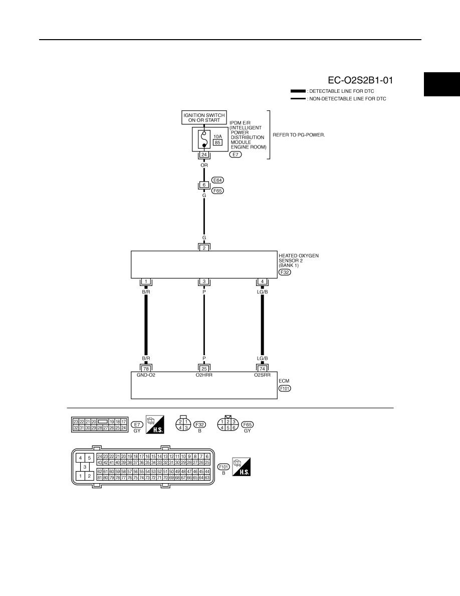
Wiring Diagram
INFOID:0000000001326088
BANK 1
Specification data are reference values and are measured between each terminal and ground.
CAUTION:
Do not use ECM ground terminals when measuring input/output voltage. Doing so may result in dam-
age to the ECM's transistor. Use a ground other than ECM terminals, such as the ground.
TBWM1592E

EC-258
< SERVICE INFORMATION >
[VQ35DE]
DTC P0138, P0158 HO2S2
TER-
MI-
NAL
NO.
WIRE
COLOR
ITEM
CONDITION
DATA (DC Voltage)
25
P
Heated oxygen sensor 2
heater (bank 1)
[Engine is running]
• Engine speed: Below 3,600 rpm after the fol-
lowing conditions are met
- Engine: After warming up
- Keeping the engine speed between 3,500
and 4,000 rpm for 1 minute and at idle for 1
minute under no load
0 - 1.0V
[Ignition switch: ON]
• Engine stopped
[Engine is running]
• Engine speed: Above 3,600 rpm
BATTERY VOLTAGE
(11 - 14V)
74
LG/B
Heated oxygen sensor 2
(bank 1)
[Engine is running]
• Revving engine from idle to 3,000 rpm quick-
ly after the following conditions are met
- Engine: After warming up
- Keeping the engine speed between 3,500
and 4,000 rpm for 1 minute and at idle for 1
minute under no load
0 - Approximately 1.0V
78
B/R
Sensor ground
(Heated oxygen sensor)
[Engine is running]
• Warm-up condition
• Idle speed
Approximately 0V
DTC P0138, P0158 HO2S2
EC-259
< SERVICE INFORMATION >
[VQ35DE]
C
D
E
F
G
H
I
J
K
L
M
A
EC
N
P
O
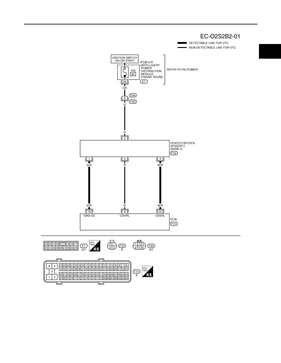
BANK 2
Specification data are reference values and are measured between each terminal and ground.
CAUTION:
Do not use ECM ground terminals when measuring input/output voltage. Doing so may result in dam-
age to the ECM's transistor. Use a ground other than ECM terminals, such as the ground.
TBWM1593E
EC-260
< SERVICE INFORMATION >
[VQ35DE]
DTC P0138, P0158 HO2S2
Diagnosis Procedure
INFOID:0000000001326089
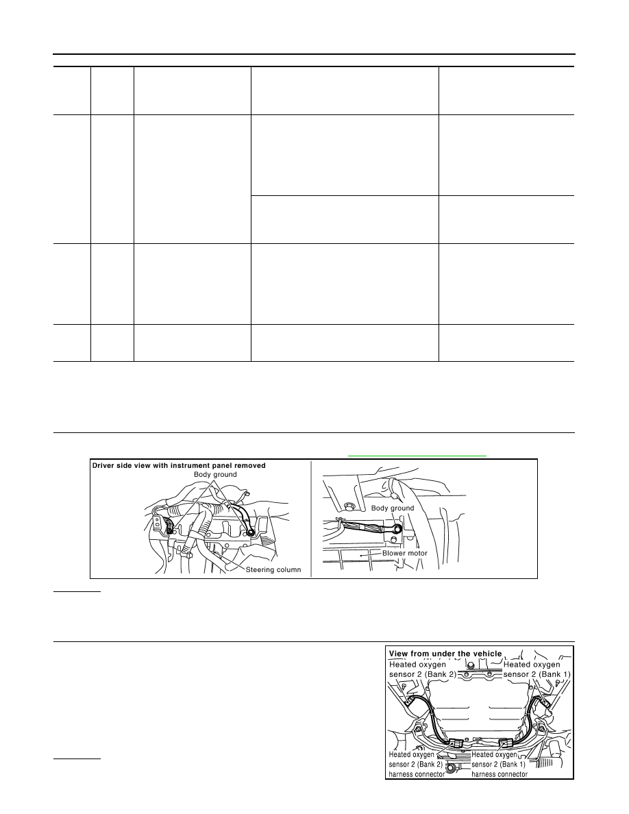
PROCEDURE FOR MALFUNCTION A
1.
CHECK GROUND CONNECTIONS
1.
Turn ignition switch OFF.
2.
Loosen and retighten ground screw on the body. Refer to
OK or NG
OK
>> GO TO 2.
NG
>> Repair or replace ground connections.
2.
CHECK HEATED OXYGEN SENSOR 2 GROUND CIRCUIT FOR OPEN AND SHORT
1.
Disconnect heated oxygen sensor 2 harness connector.
2.
Disconnect ECM harness connector.
3.
Check harness continuity between HO2S2 terminal 1 and ECM
terminal 78.
Refer to Wiring Diagram.
4.
Also check harness for short to ground and short to power.
OK or NG
OK
>> GO TO 3.
TER-
MI-
NAL
NO.
WIRE
COLOR
ITEM
CONDITION
DATA (DC Voltage)
6
R
Heated oxygen sensor 2
heater (bank 2)
[Engine is running]
• Engine speed: Below 3,600 rpm after the fol-
lowing conditions are met
- Engine: After warming up
- Keeping the engine speed between 3,500
and 4,000 rpm for 1 minute and at idle for 1
minute under no load
0 - 1.0V
[Ignition switch: ON]
• Engine stopped
[Engine is running]
• Engine speed: Above 3,600 rpm
BATTERY VOLTAGE
(11 - 14V)
55
W/R
Heated oxygen sensor 2
(bank 2)
[Engine is running]
• Revving engine from idle to 3,000 rpm quick-
ly after the following conditions are met
- Engine: After warming up
- Keeping the engine speed between 3,500
and 4,000 rpm for 1 minute and at idle for 1
minute under no load
0 - Approximately 1.0V
78
B/R
Sensor ground
(Heated oxygen sensor)
[Engine is running]
• Warm-up condition
• Idle speed
Approximately 0V
PBIB2625E
Continuity should exist.
PBIB1576E
Нет комментариевНе стесняйтесь поделиться с нами вашим ценным мнением.
Текст