Infiniti FX35 / FX45. Manual — part 759
TROUBLE DIAGNOSES WORK FLOW
LAN-13
< SERVICE INFORMATION >
[CAN FUNDAMENTAL]
C
D
E
F
G
H
I
J
L
M
A
B
LAN
N
O
P
TROUBLE DIAGNOSES WORK FLOW
Information Needed for Trouble Diagnosis
INFOID:0000000001451952
CAN communication system performs trouble diagnosis with the following tools.
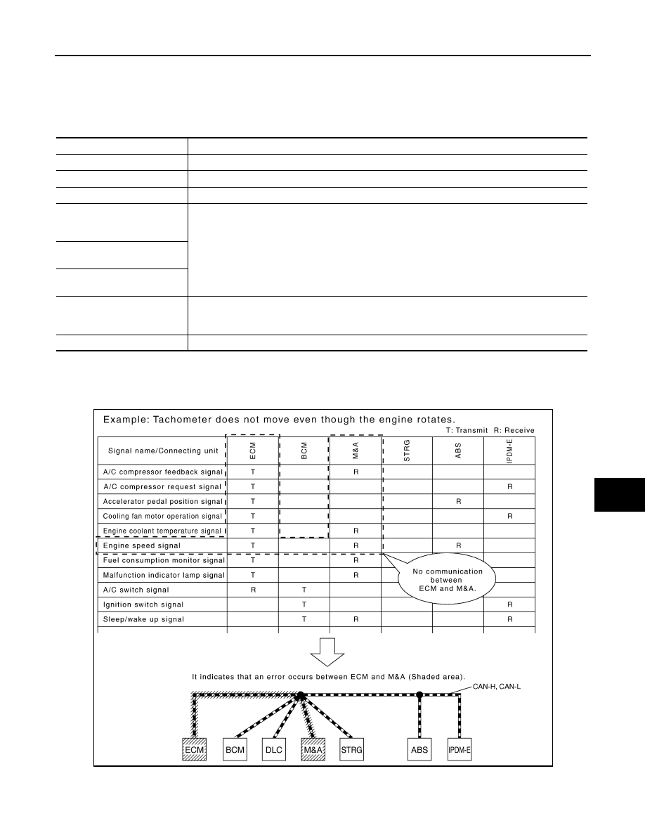
How to Use CAN Communication Signal Chart
INFOID:0000000001451953
The CAN communication signal chart lists the signals needed for trouble diagnosis. It is useful for detecting
the root cause by finding a signal related to the symptom, and by checking transmission and reception unit.
Tool
Usage
Interview sheet
For filling in vehicle information and interview with customer.
Data sheet
For copying on-board diagnosis data.
Diagnosis sheet
For detecting the root cause. (Diagnosis sheet includes system diagram for every CAN system type)
ECU list
(On the “CAN DIAG SUPPORT
MNTR”)
For checking the condition of control units and the status of CAN communication.
SELF-DIAG RESULTS
(CONSULT-III)
CAN DIAG SUPPORT MNTR
(CONSULT-III)
CAN communication signal
chart
For converting information received from a customer into CAN communication signal transmission
and reception. This information can be used to judge whether a circuit between control units is nor-
mal or abnormal.
Abbreviation list
For checking abbreviations in CAN communication signal chart and diagnosis sheet.
SKIB8715E
LAN-14
< SERVICE INFORMATION >
[CAN FUNDAMENTAL]
TROUBLE DIAGNOSES WORK FLOW
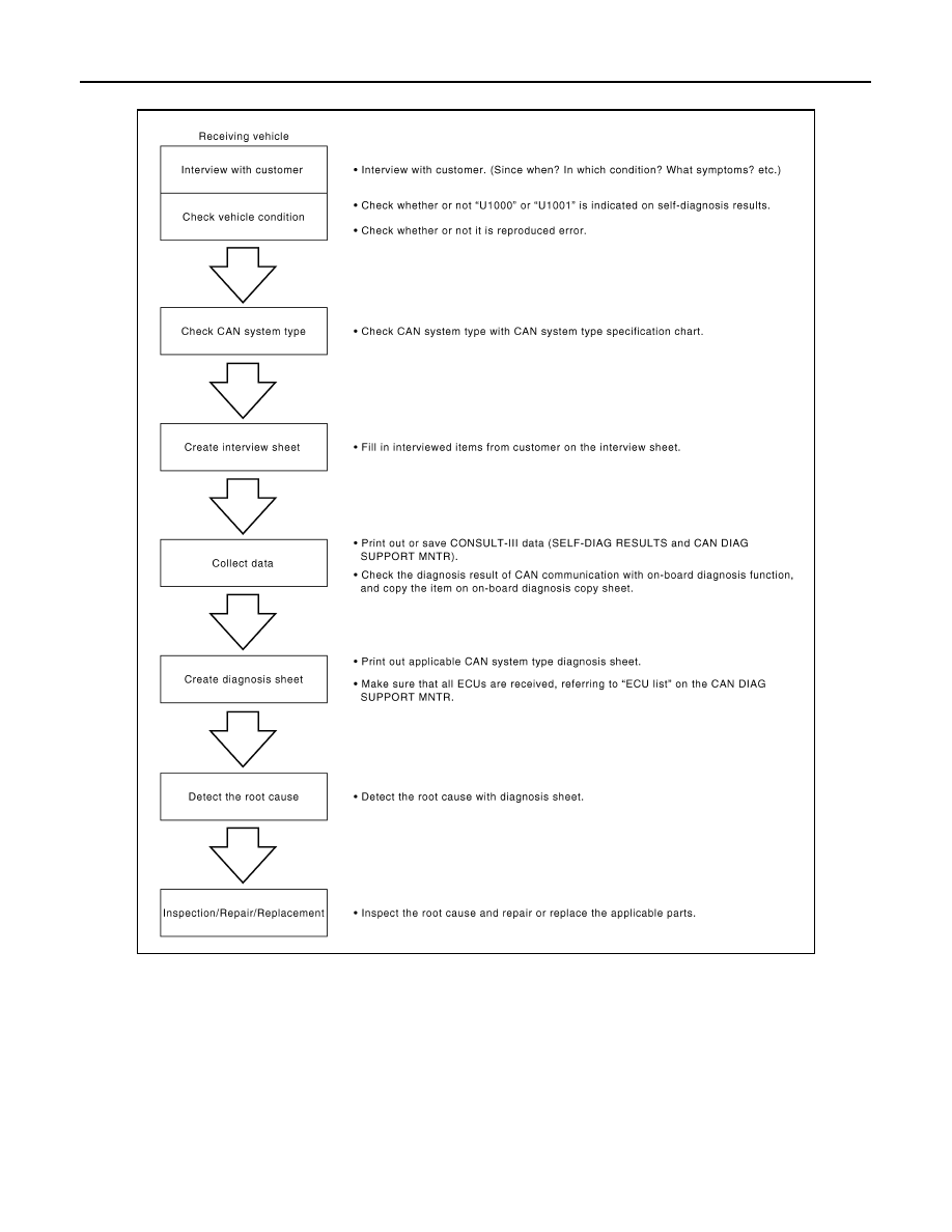
Trouble Diagnosis Flow Chart
INFOID:0000000001451954
Trouble Diagnosis Procedure
INFOID:0000000001451955
INTERVIEW WITH CUSTOMER
Interview with the customer is important to detect the root cause of CAN communication system errors and to
understand vehicle condition and symptoms for proper trouble diagnosis.
Points in interview
• What: Parts name, system name
• When: Date, Frequency
• Where: Road condition, Place
• In what condition: Driving condition/environment
PKID1210E
TROUBLE DIAGNOSES WORK FLOW
LAN-15
< SERVICE INFORMATION >
[CAN FUNDAMENTAL]
C
D
E
F
G
H
I
J
L
M
A
B
LAN
N
O
P
• Result: Symptom
NOTE:
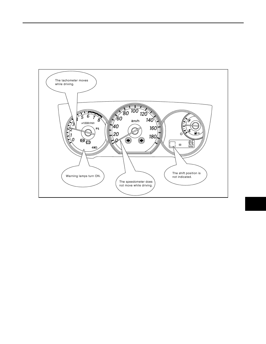
• Check normal units as well as error symptoms.
- Example: Circuit between ECM and the combination meter is judged normal if the customer indicates
tachometer functions normally.
• When a CAN communication system error is present, multiple control units may malfunction or go into fail-
safe mode.
• Indication of the combination meter is important to detect the root cause because it is the most obvious to
the customer, and it performs CAN communication with many units.
INSPECTION OF VEHICLE CONDITION
• Check whether or not “U1000” or “U1001” is indicated on “SELF-DIAG RESULTS” by CONSULT-III.
NOTE:
Root cause cannot be detected using the procedure in this section if “U1000” or “U1001” is not indicated.
• Check whether the symptom is reproduced or not.
NOTE:
• Do not turn the ignition switch OFF or disconnect the battery cable while reproducing the error. The error
may temporarily correct itself, making it difficult to determine the root cause.
• The procedures for present errors differ from the procedures for past errors. Refer to "DETECT THE
ROOT CAUSE".
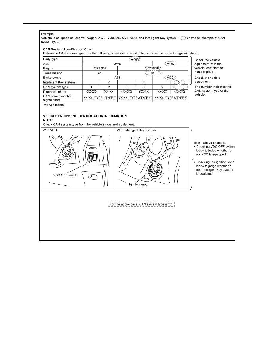
CHECK OF CAN SYSTEM TYPE (HOW TO USE CAN SYSTEM TYPE SPECIFICATION CHART)
Determine CAN system type based on vehicle equipment. Then choose the correct diagnosis sheet.
NOTE:
There are two styles for CAN system type specification charts. Depending on the number of available system
types, either style A or style B may be used.
CAN System Type Specification Chart (Style A)
NOTE:
SKIB8717E
LAN-16
< SERVICE INFORMATION >
[CAN FUNDAMENTAL]
TROUBLE DIAGNOSES WORK FLOW
CAN system type is easily checked with the vehicle equipment identification information shown in the chart.
CAN System Type Specification Chart (Style B)
NOTE:
SKIB8888E
Нет комментариевНе стесняйтесь поделиться с нами вашим ценным мнением.
Текст