Infiniti FX35, FX50 (S51). Manual — part 1097

UPPER LINK
FSU-35
< REMOVAL AND INSTALLATION >
[AWD]
C
D
F
G
H
I
J
K
L
M
A
B
FSU
N
O
P
• Hook a spring balance (A) at cutout on ball stud. Confirm spring
balance measurement value is within specifications when ball stud
begins moving.
- If swing torque exceeds standard range, replace upper link assem-
bly.
Axial End Play Inspection
• Move tip of ball stud in axial direction to check for looseness.
- If axial end play exceeds standard range, replace upper link assembly.
INSPECTION AFTER INSTALLATION
1.
Check shock absorber actuator harness connector for proper connection (with Continuous Damping Con-
trol).
2.
Check wheel sensor harness for proper connection. Refer to
BRC-131, "FRONT WHEEL SENSOR :
.
3.
Check wheel alignment. Refer to
4.
Adjust neutral position of steering angle sensor. Refer to
BRC-9, "ADJUSTMENT OF STEERING ANGLE
SENSOR NEUTRAL POSITION : Special Repair Requirement"
.
Swing torque
: Refer to
JPEIA0005ZZ
Axial end play
: Refer to
FSU-36
< REMOVAL AND INSTALLATION >
[AWD]
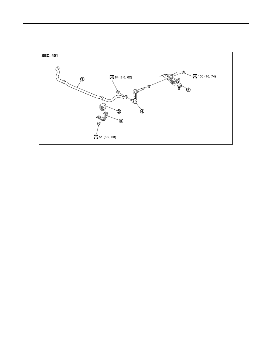
FRONT STABILIZER
FRONT STABILIZER
Exploded View
INFOID:0000000005246456
Removal and Installation
INFOID:0000000005246457
REMOVAL
1.
Remove under cover.
2.
Remove stabilizer connecting rod with power tool.
CAUTION:
Apply a matching mark to identify the installation position.
3.
Remove stabilizer clamp and stabilizer bushing.
4.
Remove stabilizer bar.
INSTALLATION
Note the following, and install in the reverse order of removal.
• Check the matching mark when installing.
• Tighten the mounting nut to the specified torque while holding a hexagonal part of stabilizer connecting rod
side.
Inspection
INFOID:0000000005246458
INSPECTION AFTER REMOVAL
Check stabilizer bar, stabilizer connecting rod, stabilizer bushing and stabilizer clamp for deformation, cracks
or damage. Replace it if necessary.
1.
Stabilizer bar
2.
Stabilizer bushing
3.
Stabilizer clamp
4.
Stabilizer connecting rod
5.
Transverse link
Refer to
for symbols in the figure.
JPEIA0107GB
FRONT SUSPENSION MEMBER
FSU-37
< UNIT REMOVAL AND INSTALLATION >
[AWD]
C
D
F
G
H
I
J
K
L
M
A
B
FSU
N
O
P
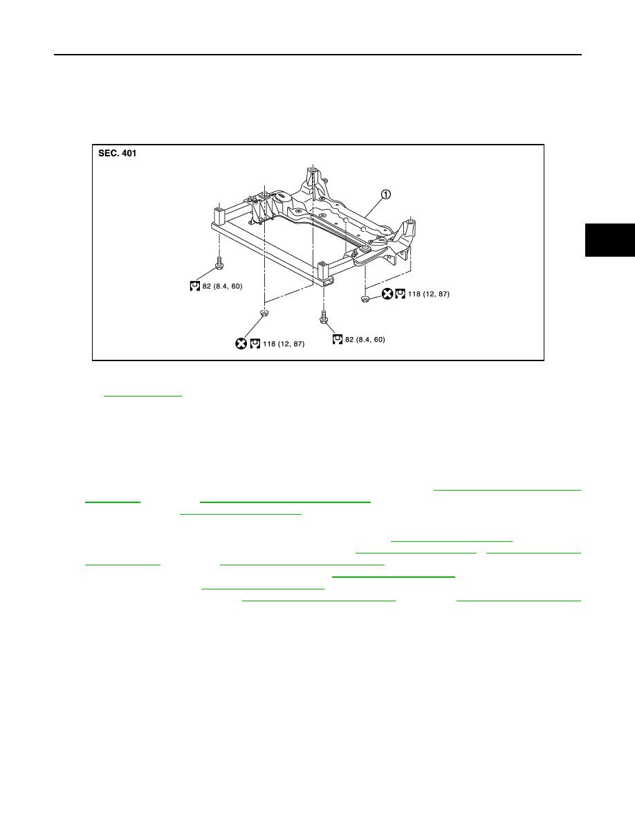
UNIT REMOVAL AND INSTALLATION
FRONT SUSPENSION MEMBER
Exploded View
INFOID:0000000005246459
Removal and Installation
INFOID:0000000005246460
REMOVAL
1.
Remove tire with power tool.
2.
At first, remove the following parts as a set.
• Engine, transmission assembly, transfer and front final drive: refer to
EM-196, "Removal and Installation"
(VK50VE).
• Drive shaft: refer to
.
3.
Remove the following parts.
• Steering knuckle and wheel hub and bearing assembly: refer to
.
• Steering gear assembly and hydraulic line: refer to
,
ST-49, "VK50VE : Exploded View"
(VK50VE).
• Stabilizer bar and stabilizer connecting rod: refer to
• Transverse link: refer to
• Engine mount insulator: refer to
(VQ35HR),
(VK50VE).
INSTALLATION
Note the following, and install in the reverse order of removal.
• Perform final tightening of bolts and nut at the vehicle installation position (rubber bushing), under unladen
condition with tires on level ground.
Inspection
INFOID:0000000005246461
INSPECTION AFTER REMOVAL
Check the front suspension member for significant deformation, cracks, or damages. Replace if necessary.
INSPECTION AFTER INSTALLATION
1.
Check shock absorber actuator harness connector for proper connection (with Continuous Damping Con-
trol).
1.
Front suspension member
Refer to
JPEIA0111GB

FSU-38
< UNIT REMOVAL AND INSTALLATION >
[AWD]
FRONT SUSPENSION MEMBER
2.
Check wheel sensor harness for proper connection. Refer to
BRC-131, "FRONT WHEEL SENSOR :
.
3.
Check wheel alignment. Refer to
4.
Adjust the neutral position of the steering angle sensor. Refer to
BRC-9, "ADJUSTMENT OF STEERING
ANGLE SENSOR NEUTRAL POSITION : Special Repair Requirement"
.
Нет комментариевНе стесняйтесь поделиться с нами вашим ценным мнением.
Текст