Infiniti FX35, FX50 (S51). Manual — part 1338
LAN-294
< DTC/CIRCUIT DIAGNOSIS >
[CAN SYSTEM (TYPE 9)]
STRG BRANCH LINE CIRCUIT
STRG BRANCH LINE CIRCUIT
Diagnosis Procedure
INFOID:0000000005577203
1.
CHECK CONNECTOR
1.
Turn the ignition switch OFF.
2.
Disconnect the battery cable from the negative terminal.
3.
Check the terminals and connectors of the steering angle sensor for damage, bend and loose connection
(unit side and connector side).
Is the inspection result normal?
YES
>> GO TO 2.
NO
>> Repair the terminal and connector.
2.
CHECK HARNESS FOR OPEN CIRCUIT
1.
Disconnect the connector of steering angle sensor.
2.
Check the resistance between the steering angle sensor harness connector terminals.
Is the measurement value within the specification?
YES
>> GO TO 3.
NO
>> Repair the steering angle sensor branch line.
3.
CHECK POWER SUPPLY AND GROUND CIRCUIT
Check the power supply and the ground circuit of the steering angle sensor. Refer to
gram - BRAKE CONTROL SYSTEM -"
.
Is the inspection result normal?
YES (Present error)>>Replace the steering angle sensor. Refer to
.
YES (Past error)>>Error was detected in the steering angle sensor branch line.
NO
>> Repair the power supply and the ground circuit.
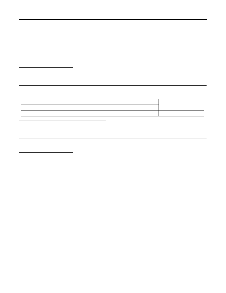
Steering angle sensor harness connector
Resistance (
Ω
)
Connector No.
Terminal No.
M37
1
2
Approx. 54 – 66
LAN
TPMS BRANCH LINE CIRCUIT
LAN-295
< DTC/CIRCUIT DIAGNOSIS >
[CAN SYSTEM (TYPE 9)]
C
D
E
F
G
H
I
J
K
L
B
A
O
P
N
TPMS BRANCH LINE CIRCUIT
Diagnosis Procedure
INFOID:0000000005577204
1.
CHECK CONNECTOR
1.
Turn the ignition switch OFF.
2.
Disconnect the battery cable from the negative terminal.
3.
Check the terminals and connectors of the low tire pressure warning control unit for damage, bend and
loose connection (unit side and connector side).
Is the inspection result normal?
YES
>> GO TO 2.
NO
>> Repair the terminal and connector.
2.
CHECK HARNESS FOR OPEN CIRCUIT
1.
Disconnect the connector of low tire pressure warning control unit.
2.
Check the resistance between the low tire pressure warning control unit harness connector terminals.
Is the measurement value within the specification?
YES
>> GO TO 3.
NO
>> Repair the low tire pressure warning control unit branch line.
3.
CHECK POWER SUPPLY AND GROUND CIRCUIT
Check the power supply and the ground circuit of the low tire pressure warning control unit. Refer to
.
Is the inspection result normal?
YES (Present error)>>Replace the low tire pressure warning control unit. Refer to
.
YES (Past error)>>Error was detected in the low tire pressure warning control unit branch line.
NO
>> Repair the power supply and the ground circuit.
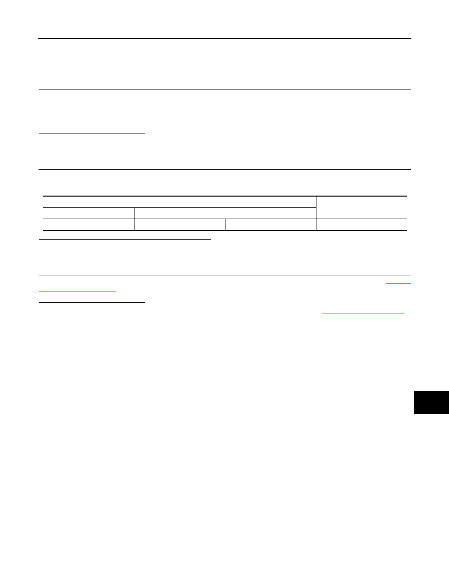
Low tire pressure warning control unit harness connector
Resistance (
Ω
)
Connector No.
Terminal No.
M96
2
1
Approx. 54 – 66
LAN-296
< DTC/CIRCUIT DIAGNOSIS >
[CAN SYSTEM (TYPE 9)]
ADP BRANCH LINE CIRCUIT
ADP BRANCH LINE CIRCUIT
Diagnosis Procedure
INFOID:0000000005577205
1.
CHECK CONNECTOR
1.
Turn the ignition switch OFF.
2.
Disconnect the battery cable from the negative terminal.
3.
Check the following terminals and connectors for damage, bend and loose connection (unit side and con-
nector side).
-
Driver seat control unit
-
Harness connector B460
-
Harness connector B11
Is the inspection result normal?
YES
>> GO TO 2.
NO
>> Repair the terminal and connector.
2.
CHECK HARNESS FOR OPEN CIRCUIT
1.
Disconnect the connector of driver seat control unit.
2.
Check the resistance between the driver seat control unit harness connector terminals.
Is the measurement value within the specification?
YES
>> GO TO 3.
NO
>> Repair the driver seat control unit branch line.
3.
CHECK POWER SUPPLY AND GROUND CIRCUIT
Check the power supply and the ground circuit of the driver seat control unit. Refer to
CONTROL UNIT : Diagnosis Procedure"
Is the inspection result normal?
YES (Present error)>>Replace the driver seat control unit. Refer to
YES (Past error)>>Error was detected in the driver seat control unit branch line.
NO
>> Repair the power supply and the ground circuit.
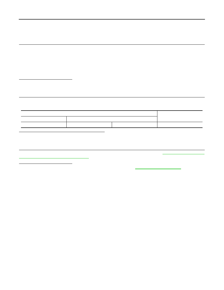
Driver seat control unit harness connector
Resistance (
Ω
)
Connector No.
Terminal No.
B451
3
19
Approx. 54 – 66
LAN
CGW BRANCH LINE CIRCUIT (CAN COMMUNICATION CIRCUIT 1)
LAN-297
< DTC/CIRCUIT DIAGNOSIS >
[CAN SYSTEM (TYPE 9)]
C
D
E
F
G
H
I
J
K
L
B
A
O
P
N
CGW BRANCH LINE CIRCUIT (CAN COMMUNICATION CIRCUIT 1)
Diagnosis Procedure
INFOID:0000000005577208
1.
CHECK DTC
Check DTC of the CAN gateway with CONSULT-III.
Is U1010 or B2600 indicated?
YES
>> Perform a diagnosis of the indicated DTC.
NO
>> GO TO 2.
2.
CHECK CONNECTOR
1.
Turn the ignition switch OFF.
2.
Disconnect the battery cable from the negative terminal.
3.
Check the terminals and connectors of the CAN gateway for damage, bend and loose connection (unit
side and connector side).
Is the inspection result normal?
YES
>> GO TO 3.
NO
>> Repair the terminal and connector.
3.
CHECK HARNESS FOR OPEN CIRCUIT
1.
Disconnect the connector of CAN gateway.
2.
Check the resistance between the CAN gateway harness connector terminals.
Is the measurement value within the specification?
YES
>> GO TO 4.
NO
>> Repair the CAN gateway branch line (CAN communication circuit 1).
4.
CHECK POWER SUPPLY AND GROUND CIRCUIT
Check the power supply and the ground circuit of the CAN gateway. Refer to
.
Is the inspection result normal?
YES (Present error)>>Replace the CAN gateway. Refer to
.
YES (Past error)>>Error was detected in the CAN gateway branch line (CAN communication circuit 1).
NO
>> Repair the power supply and the ground circuit.
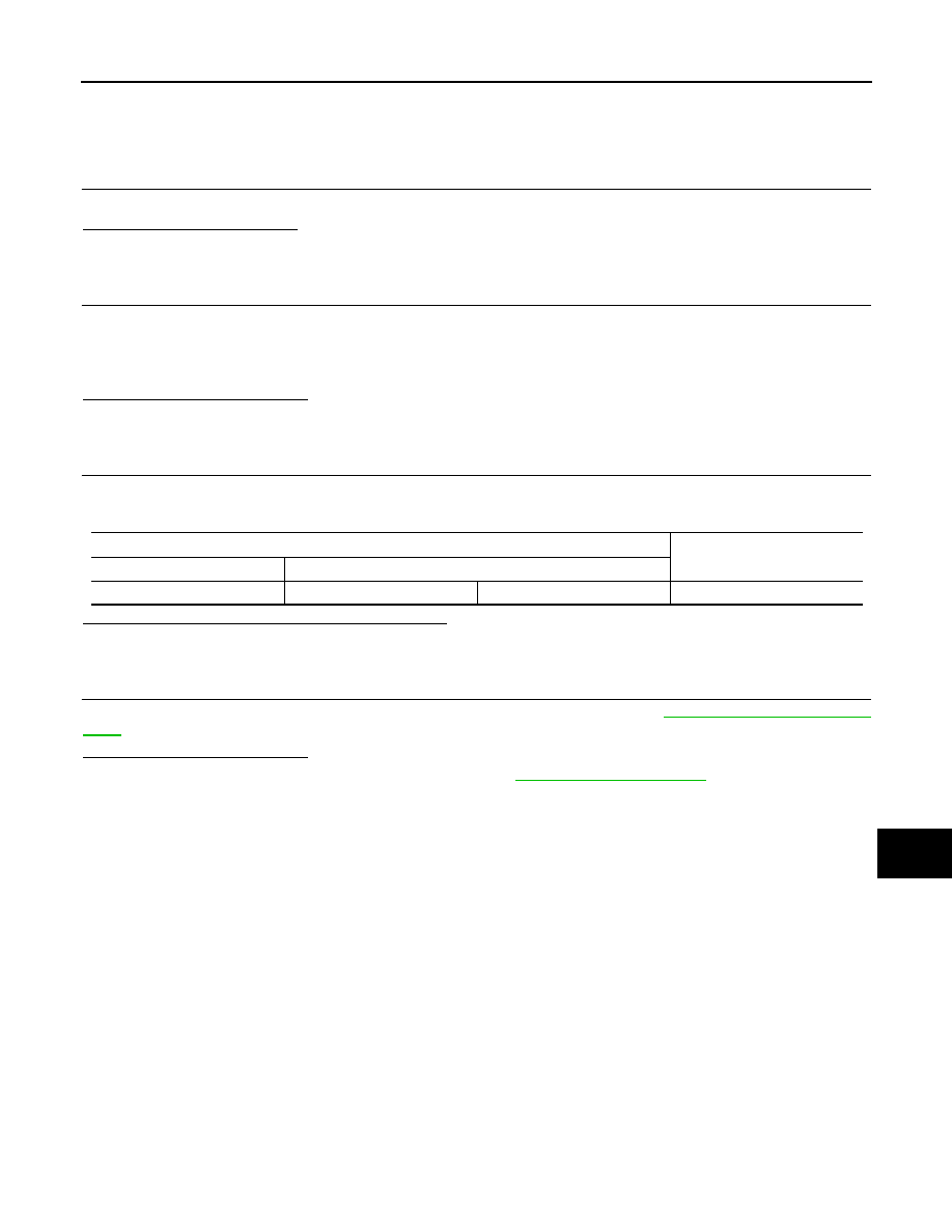
CAN gateway harness connector
Resistance (
Ω
)
Connector No.
Terminal No.
M125
1
7
Approx. 54 – 66
Нет комментариевНе стесняйтесь поделиться с нами вашим ценным мнением.
Текст