Infiniti FX35, FX50 (S51). Manual — part 1805
SHIFT PATTERN CONTROL
TM-27
< SYSTEM DESCRIPTION >
[7AT: RE7R01A (VQ35HR)]
C
E
F
G
H
I
J
K
L
M
A
B
TM
N
O
P
- When the selector lever shifts to DOWN side while driving in 1GR.
- When the selector lever shifts to UP side while driving in 7GR.
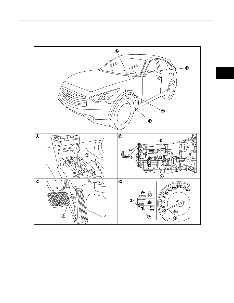
MANUAL MODE : Component Parts Location
INFOID:0000000005477011
NOTE:
• The following components are included in A/T shift selector assembly.
- Manual mode select switch
- Manual mode position select switch
- Shift position switch
• The following components are included in control valve with TCM.
- TCM
1.
Selector lever position indicator
2.
A/T shift selector assembly
3.
A/T assembly connector
4.
Control valve with TCM*
5.
Accelerator pedal position sensor
6.
Manual mode indicator
7.
Shift position indicator
8.
A/T CHECK indicator lamp
A.
Center console
B.
A/T assembly
C.
Accelerator pedal
D.
Combination meter
JSDIA0782ZZ

TM-28
< SYSTEM DESCRIPTION >
[7AT: RE7R01A (VQ35HR)]
SHIFT PATTERN CONTROL
- Input speed sensor 1, 2
- Output speed sensor
- A/T fluid temperature sensor
- Transmission range switch
- Direct clutch solenoid valve
- High and low reverse clutch solenoid valve
- Input clutch solenoid valve
- Front brake solenoid valve
- Low brake solenoid valve
- Anti-interlock solenoid valve
- 2346 brake solenoid valve
- Line pressure solenoid valve
- Torque converter clutch solenoid valve
*: Control valve with TCM is included in A/T assembly.
MANUAL MODE : Component Description
INFOID:0000000005520188
Name
Function
TCM
The TCM consists of a microcomputer and connectors for signal input and output and
for power supply. The TCM controls the A/T.
Output speed sensor
A/T fluid temperature sensor
Input clutch solenoid valve
Front brake solenoid valve
Direct clutch solenoid valve
High and low reverse clutch solenoid valve
Low brake solenoid valve
Anti-interlock solenoid valve
2346 brake solenoid valve
Line pressure solenoid valve
Torque converter clutch solenoid valve
ECM
BCM
Unified meter and A/C amp.
LOCK-UP CONTROL
TM-29
< SYSTEM DESCRIPTION >
[7AT: RE7R01A (VQ35HR)]
C
E
F
G
H
I
J
K
L
M
A
B
TM
N
O
P
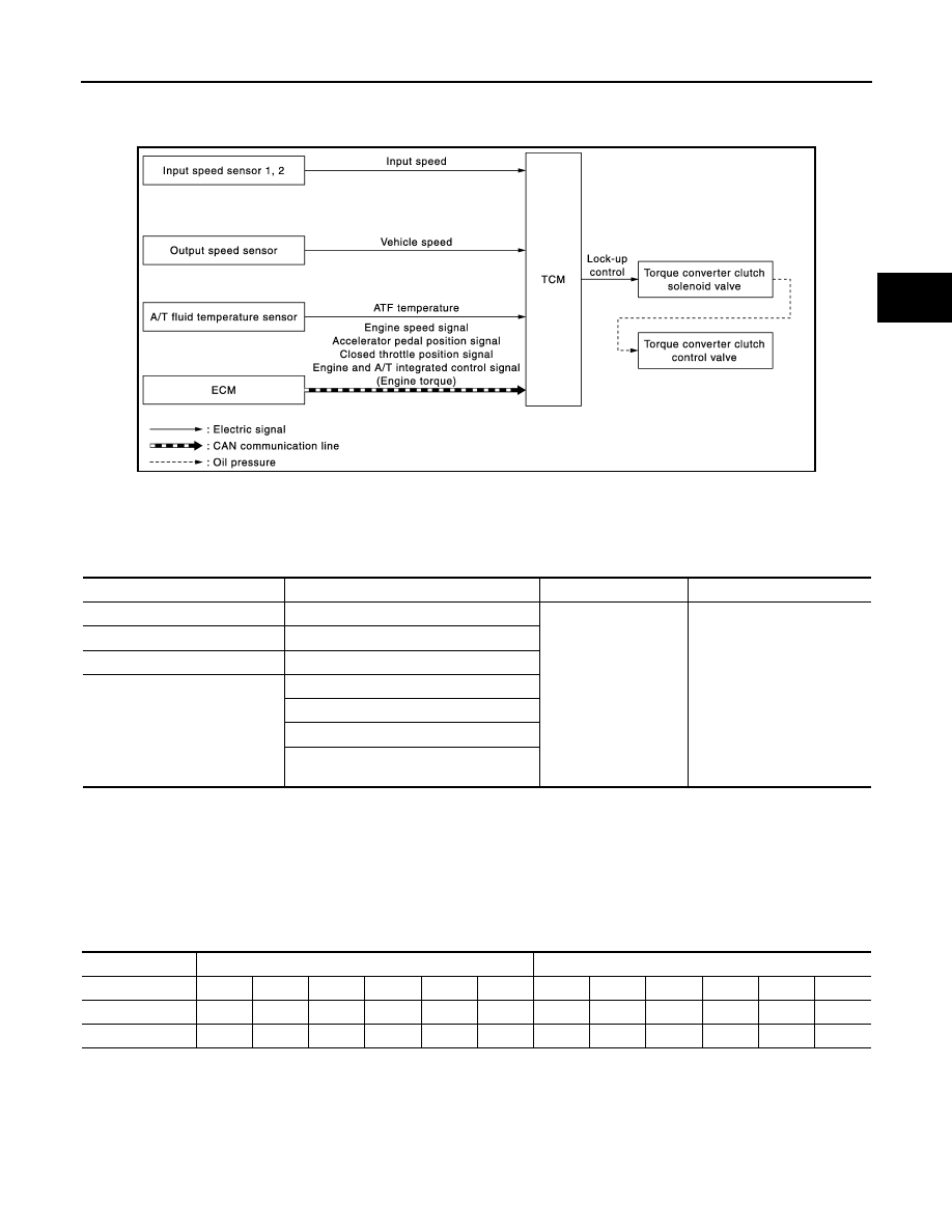
LOCK-UP CONTROL
System Diagram
INFOID:0000000005250010
System Description
INFOID:0000000005250011
INPUT/OUTPUT SIGNAL CHART
*: This signal is transmitted via CAN communication line.
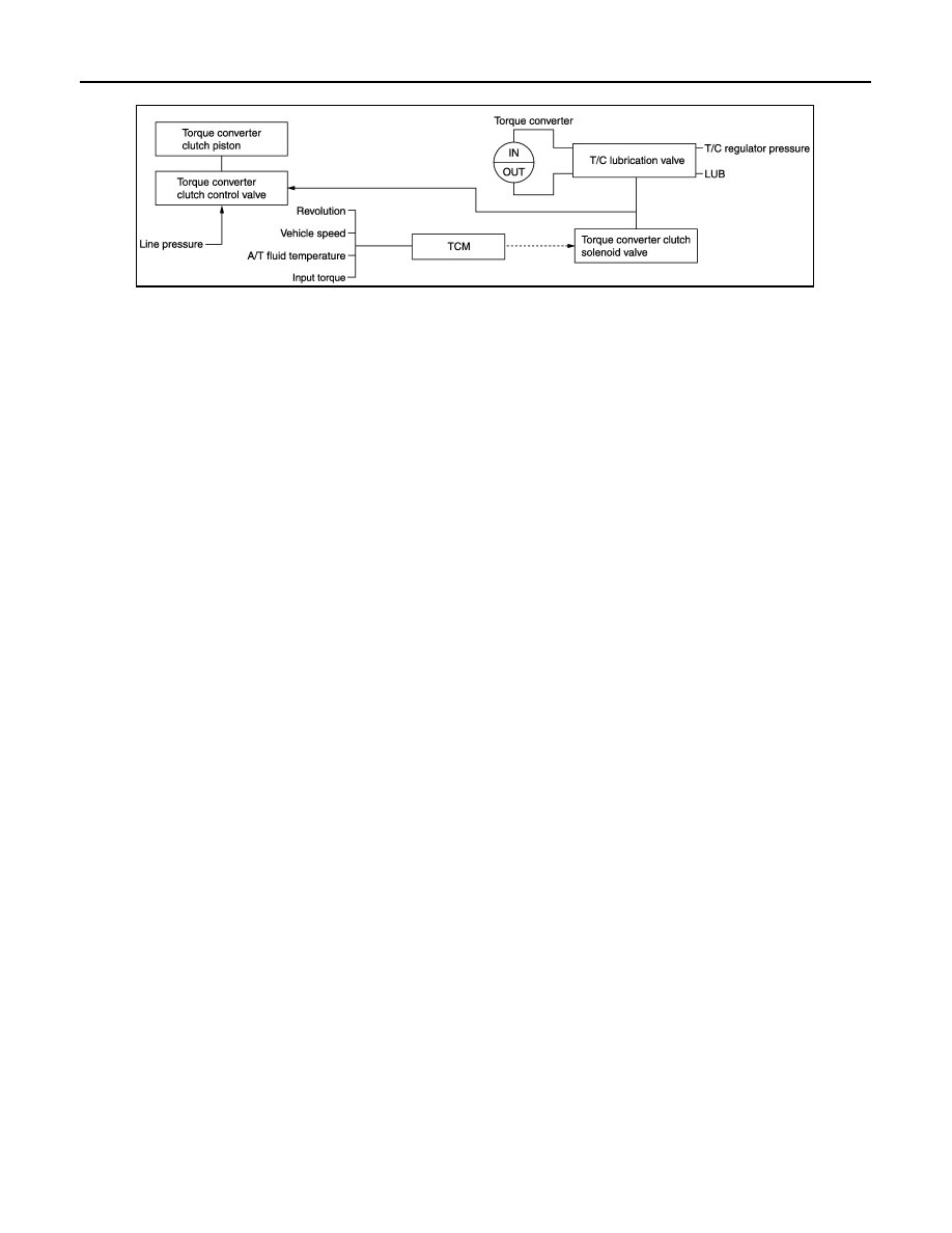
SYSTEM DESCRIPTION
The torque converter clutch piston in the torque converter is engaged to eliminate torque converter slip to
increase power transmission efficiency.
The torque converter clutch control valve operation is controlled by the torque converter clutch solenoid valve,
which is controlled by a signal from TCM, and the torque converter clutch control valve engages or releases
the torque converter clutch piston.
Lock-up operation condition table
Torque Converter Clutch Control Valve Control
Lock-up control system diagram
JSDIA1350GB
Sensor
Input signal to TCM
TCM function
Actuator
Input speed sensor 1, 2
Input speed
Lock-up control
Torque converter clutch sole-
noid valve
↓
Torque converter clutch con-
trol valve
Output speed sensor
Vehicle speed
A/T fluid temperature sensor
ATF temperature
ECM
Engine speed signal*
Accelerator pedal position signal*
Closed throttle position signal*
Engine and A/T integrated control signal
(Engine torque)*
Selector lever
“D” position
“M” position
Gear position
7
6
5
4
3
2
7
6
5
4
3
2
Lock-up
×
–
–
–
–
–
×
×
×
×
×
×
Slip lock-up
×
×
×
×
×
×
×
×
×
×
×
×
TM-30
< SYSTEM DESCRIPTION >
[7AT: RE7R01A (VQ35HR)]
LOCK-UP CONTROL
Lock-up released
• In the lock-up released state, the torque converter clutch control valve is set into the unlocked state by the
torque converter clutch solenoid and the lock-up apply pressure is drained.
in this way, the torque converter clutch piston is not coupled.
Lock-up Applied
• In the lock-up applied state, the torque converter clutch control valve is set into the locked state by the
torque converter clutch solenoid and lock-up apply pressure is generated.
In this way, the torque converter clutch piston is pressed and coupled.
Smooth Lock-up Control
When shifting from the lock-up released state to the lock-up applied state, the current output to the torque con-
verter clutch solenoid is controlled with the TCM. In this way, when shifting to the lock-up applied state, the
torque converter clutch is temporarily set to the half-clutched state to reduce the shock.
Half-clutched State
• The current output from the TCM to the torque converter clutch solenoid is varied to steadily increase the
torque converter clutch solenoid pressure.
In this way, the lock-up apply pressure gradually rises and while the torque converter clutch piston is put into
half-clutched states, the torque converter clutch piston operating pressure is increased and the coupling is
completed smoothly.
Slip Lock-up Control
• In the slip region, the torque converter clutch solenoid current is controlled with the TCM to put it into the
half-clutched state. This absorbs the engine torque fluctuation and lock-up operates from low speed.
This raises the fuel efficiency for 2GR, 3GR, 4GR, 5GR, 6GR and 7GR.
JSDIA0847GB
Нет комментариевНе стесняйтесь поделиться с нами вашим ценным мнением.
Текст