Infiniti FX35, FX50 (S51). Manual — part 1804
SHIFT PATTERN CONTROL
TM-23
< SYSTEM DESCRIPTION >
[7AT: RE7R01A (VQ35HR)]
C
E
F
G
H
I
J
K
L
M
A
B
TM
N
O
P
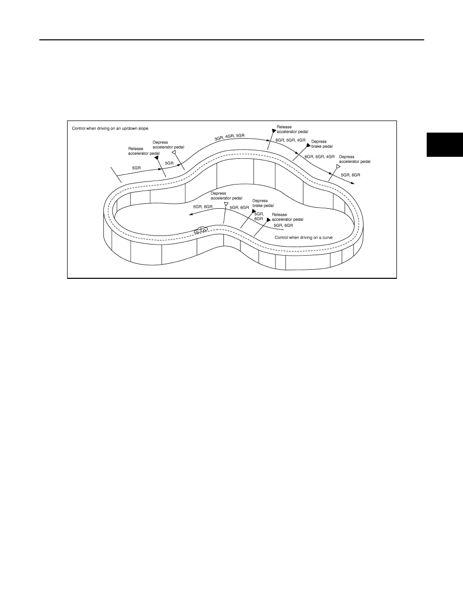
ASC judges up/down slope according to engine torque data transmitted from the ECM and vehicle speed.
Fixing at 4GR, 5GR or 6GR on an up-slope prevents shift hunting and controls the vehicle to gain optimum
driving force. On a down-slope, automatic shift-down to 4GR, 5GR or 6GR controls to gain optimum engine
brake.
• When driving on a curve
TCM receives the side G sensor signal from the ABS actuator and electric unit (control unit). It locks to 4GR,
5GR or 6GR position in moderate cornering or to 3GR position in sharp cornering based on this signal. This
prevents any upshift and kickdown during cornering, maintaining smooth vehicle travel.
DS Mode
• Changes to the shift schedule that mainly utilizes the high engine speed zone when ASC is active.
• DS mode can be switched according to the following method.
- When the selector lever is in the “D” position, shifting the selector lever to manual shift gate enables switch-
ing to DS mode.
- When in DS mode, shifting the selector lever to the main gate enables to cancel DS mode.
JSDIA1362GB
TM-24
< SYSTEM DESCRIPTION >
[7AT: RE7R01A (VQ35HR)]
SHIFT PATTERN CONTROL
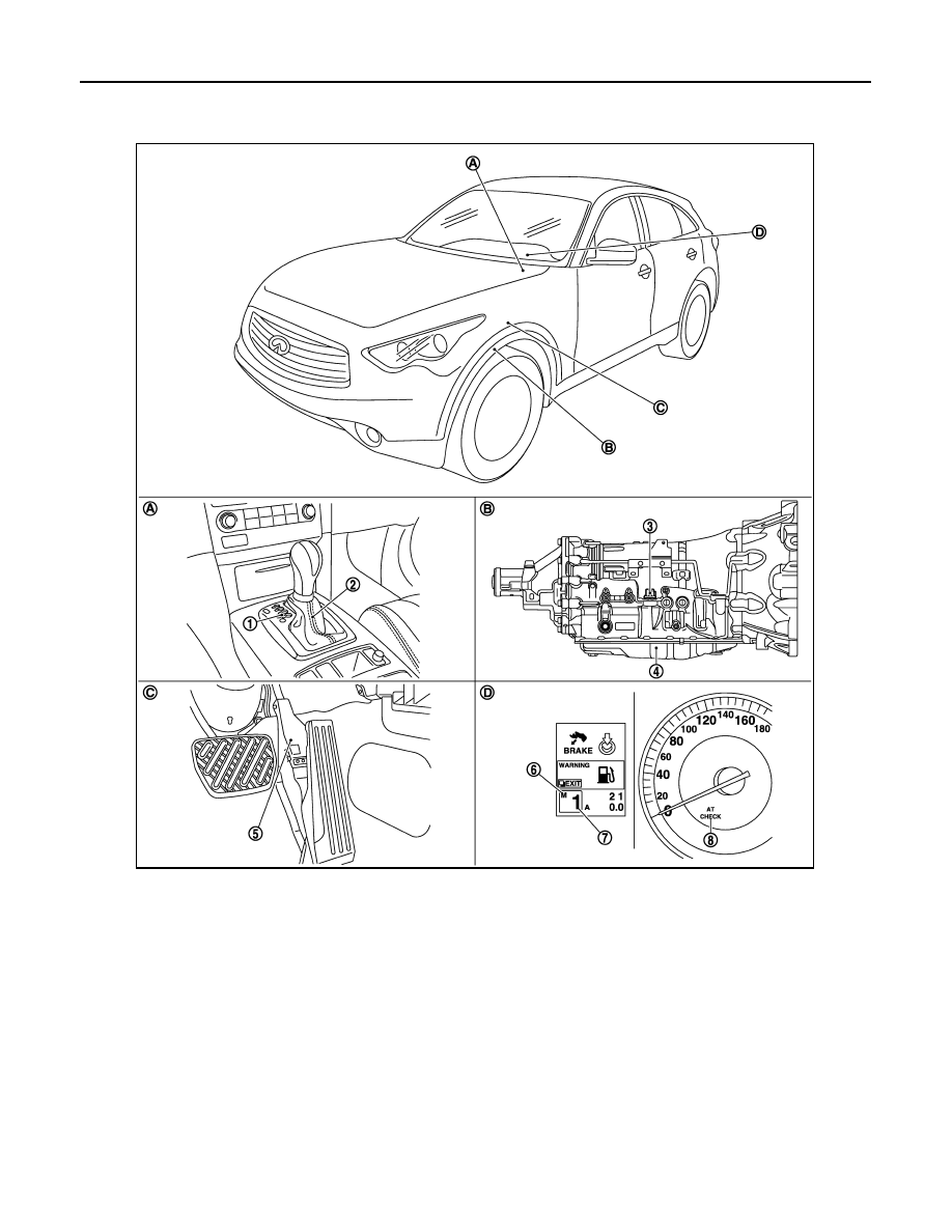
ASC (ADAPTIVE SHIFT CONTROL) : Component Parts Location
INFOID:0000000005477010
NOTE:
• The following components are included in A/T shift selector assembly.
- Manual mode select switch
- Manual mode position select switch
- Shift position switch
• The following components are included in control valve with TCM.
- TCM
- Input speed sensor 1, 2
- Output speed sensor
1.
Selector lever position indicator
2.
A/T shift selector assembly
3.
A/T assembly connector
4.
Control valve with TCM*
5.
Accelerator pedal position sensor
6.
Manual mode indicator
7.
Shift position indicator
8.
A/T CHECK indicator lamp
A.
Center console
B.
A/T assembly
C.
Accelerator pedal
D.
Combination meter
JSDIA0782ZZ

SHIFT PATTERN CONTROL
TM-25
< SYSTEM DESCRIPTION >
[7AT: RE7R01A (VQ35HR)]
C
E
F
G
H
I
J
K
L
M
A
B
TM
N
O
P
- A/T fluid temperature sensor
- Transmission range switch
- Direct clutch solenoid valve
- High and low reverse clutch solenoid valve
- Input clutch solenoid valve
- Front brake solenoid valve
- Low brake solenoid valve
- Anti-interlock solenoid valve
- 2346 brake solenoid valve
- Line pressure solenoid valve
- Torque converter clutch solenoid valve
*: Control valve with TCM is included in A/T assembly.
ASC (ADAPTIVE SHIFT CONTROL) : Component Description
INFOID:0000000005250005
MANUAL MODE
Name
Function
TCM
The TCM consists of a microcomputer and connectors for signal input and output and
for power supply. The TCM controls the A/T.
Output speed sensor
Input speed sensor 1
Input speed sensor 2
A/T fluid temperature sensor
Input clutch solenoid valve
Front brake solenoid valve
Direct clutch solenoid valve
High and low reverse clutch solenoid valve
Low brake solenoid valve
Anti-interlock solenoid valve
2346 brake solenoid valve
Line pressure solenoid valve
Torque converter clutch solenoid valve
ECM
BCM
ABS actuator and electric unit (control unit)

TM-26
< SYSTEM DESCRIPTION >
[7AT: RE7R01A (VQ35HR)]
SHIFT PATTERN CONTROL
MANUAL MODE : System Diagram
INFOID:0000000005250006
MANUAL MODE : System Description
INFOID:0000000005250007
INPUT/OUTPUT SIGNAL CHART
*: This signal is transmitted via CAN communication line.
SYSTEM DESCRIPTION
Manual Mode
• The TCM receives the manual mode signal, non-manual mode signal, manual mode shift up signal and
manual mode shift down signal from unified meter and A/C amp. via CAN communication line. The TCM
shifts shift pattern control to the manual mode based on these signals, and then shifts the A/T by operating
each solenoid valve according to the shift operation of the driver.
• The TCM prohibits the manual mode while being in fail-safe mode due to an A/T malfunction, etc. Refer to
• The TCM transmits the manual mode shift refusal signal to the unified meter and A/C amp. if the TCM
refuses the transmission from the driving status of vehicle when the selector lever shifts to UP or DOWN
side. The unified meter and A/C amp. blinks shift indicator on the combination meter and sounds the buzzer
to indicate the driver that the shifting is not performed when receiving this signal. However, the TCM does
not transmit the manual mode shift refusal signal in the conditions as per the following.
JSDIA1409GB
Sensor
Input signal to TCM
TCM function
Actuator
Output speed sensor
Vehicle speed
Shift pattern control
• High and low reverse clutch
solenoid valve
• Direct clutch solenoid valve
• Input clutch solenoid valve
• Low brake solenoid valve
• 2346 brake solenoid valve
• Front brake solenoid valve
• Torque converter clutch sole-
noid valve
• Line pressure solenoid valve
• Anti-interlock solenoid valve
A/T fluid temperature sensor
ATF temperature
ECM
Engine speed signal*
Accelerator pedal position signal*
Unified meter and A/C amp.
Manual mode signal*
Non-manual mode signal*
Manual mode shift up signal*
Manual mode shift down signal*
Нет комментариевНе стесняйтесь поделиться с нами вашим ценным мнением.
Текст