Infiniti FX35, FX50 (S51). Manual — part 983
EM-232
< UNIT DISASSEMBLY AND ASSEMBLY >
[VK50VE]
CAMSHAFT
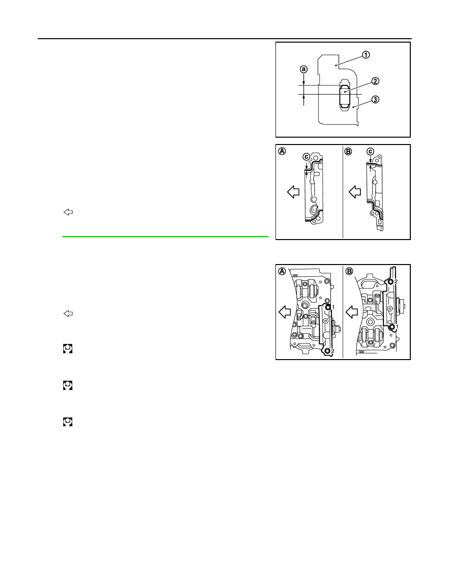
a.
Refer to the figure to replace new dowel pins (2), if removed.
b.
Apply a continuous bead of liquid gasket with tube presser
(commercial service tool) to the actuator bracket (rear) as
shown in the figure.
Use Genuine RTV Silicone Sealant or an equivalent. Refer
to
GI-16, "Recommended Chemical Products and Sealants"
.
CAUTION:
Never apply gasket to the oil passage.
c.
Tighten mounting bolts in the following steps, in numerical order
as shown.
i.
Tighten bolts in numerical order as shown.
ii.
Tighten bolts in numerical order as shown.
iii.
Tighten bolts in numerical order as shown.
6.
Install new VVEL actuator sub assembly as per the following:
CAUTION:
Regarding replacement, because VVEL actuator sub assembly and VVEL control shaft position
sensor are controlled on a one-on-one basis, replace them as a set.
NOTE:
1
: Actuator bracket
3
: VVEL ladder assembly
a
: 4.0 - 6.0 mm(0.157 - 0.236 in)
JPBIA2474ZZ
A
: Bank 2
B
: Bank 1
c
:
φ
3.4 - 4.4 mm (0.134 - 0.173 in)
: Engine front
JPBIA2132ZZ
A
: Bank 2
B
: Bank 1
: Engine front
: 1.96 N·m (0.20 kg-m, 1 ft-lb)
: 5.88 N·m (0.60 kg-m, 4 ft-lb)
: 31.4 N·m (3.2 kg-m, 23 ft-lb)
JPBIA2125ZZ
CAMSHAFT
EM-233
< UNIT DISASSEMBLY AND ASSEMBLY >
[VK50VE]
C
D
E
F
G
H
I
J
K
L
M
A
EM
N
P
O
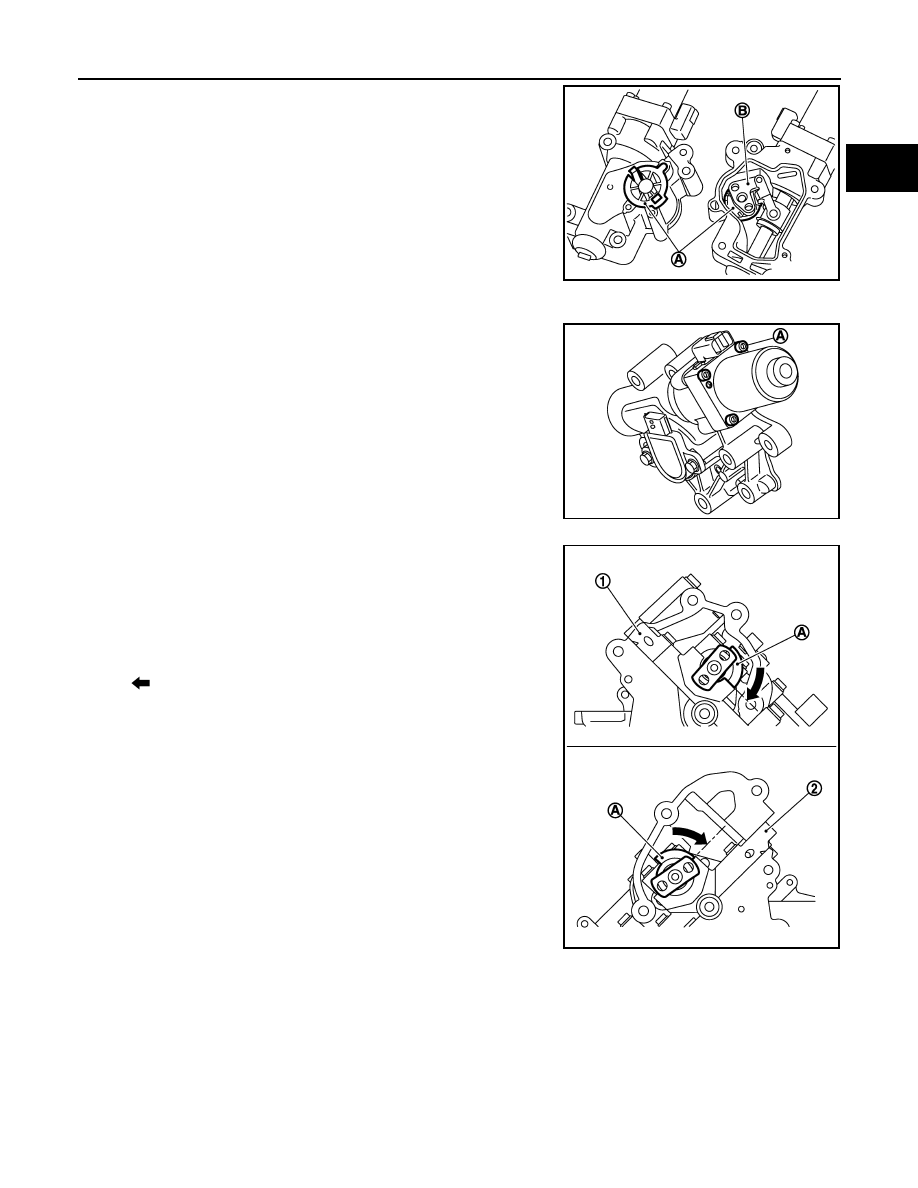
• VVEL actuator arm (B) is factory-fixed at 10 degrees from the
small lift with a holding jig (A).
• The holding jig is supplied in the new VVEL actuator sub
assembly.
CAUTION:
• Never disassemble VVEL actuator sub assembly. [Never
loosen actuator motor mounting bolts (A) shown in the
figure]
• Never impact VVEL actuator sub assembly.
a.
Move control shaft to the position of small lift stopper.
• The position where a part of the stopper of control shaft con-
tacts VVEL ladder bracket.
CAUTION:
Be careful not to damage the stopper surface.
• If control shaft cannot be moved, set crankshaft in position referring to the information below. (To dis-
place cam nose)
JPBIA1137ZZ
JPBIA1120ZZ
1
: VVEL ladder assembly (bank 2)
2
: VVEL ladder assembly (bank 1)
A
: Stopper of control shaft
: Small lift side
JPBIA2134ZZ
Bank 1
: Turn 360 degrees from No. 1 cylinder at TDC
Bank 2
: No. 1 cylinder at TDC
EM-234
< UNIT DISASSEMBLY AND ASSEMBLY >
[VK50VE]
CAMSHAFT
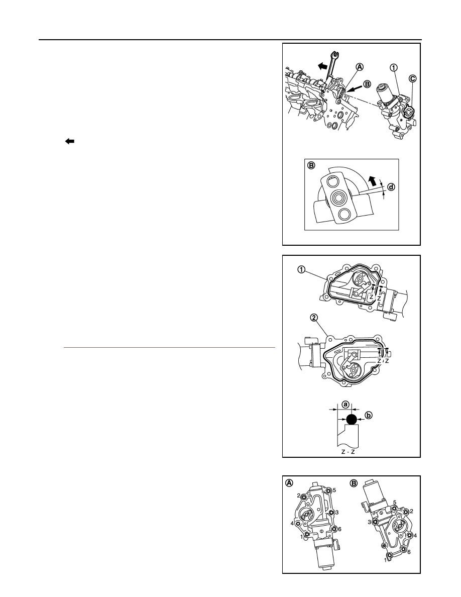
b.
Hold two flat areas of control shaft with a wrench, and rotate the
control shaft (10 degrees from the stopper) to the large lift side.
(This is for aligning the bolt hole of control shaft and the hole of
VVEL actuator arm.)
NOTE:
The figure shows an example of bank 2.
c.
Apply a continuous bead of liquid gasket with tube presser
(commercial service tool) to the VVEL actuator sub assembly as
shown in the figure.
Use Genuine RTV Silicone Sealant or an equivalent. Refer
to
GI-16, "Recommended Chemical Products and Sealants"
.
CAUTION:
Never apply gasket to the oil passage.
d.
Install new VVEL actuator sub assembly.
• Tighten mounting bolts in the following step, in numerical order
as shown.
CAUTION:
• When installing, be careful with VVEL actuator sub
assembly (bank 1) mounting bolt No. 4 because its length
is different.
1
: VVEL actuator sub assembly (bank 2)
A
: Control shaft
B
: View B
C
: Holding jig
d
: 10 degrees
: Large lift side
JPBIA2139ZZ
1
: VVEL actuator sub assembly (bank 2)
2
: VVEL actuator sub assembly (bank 1)
a
: 4.0 - 5.6 mm (0.157 - 0.220 in)
b
:
φ
3.4 - 4.4 mm (0.134 - 0.173 in)
JPBIA2140ZZ
A
: Bank 1
B
: Bank 2
JPBIA2127ZZ
CAMSHAFT
EM-235
< UNIT DISASSEMBLY AND ASSEMBLY >
[VK50VE]
C
D
E
F
G
H
I
J
K
L
M
A
EM
N
P
O
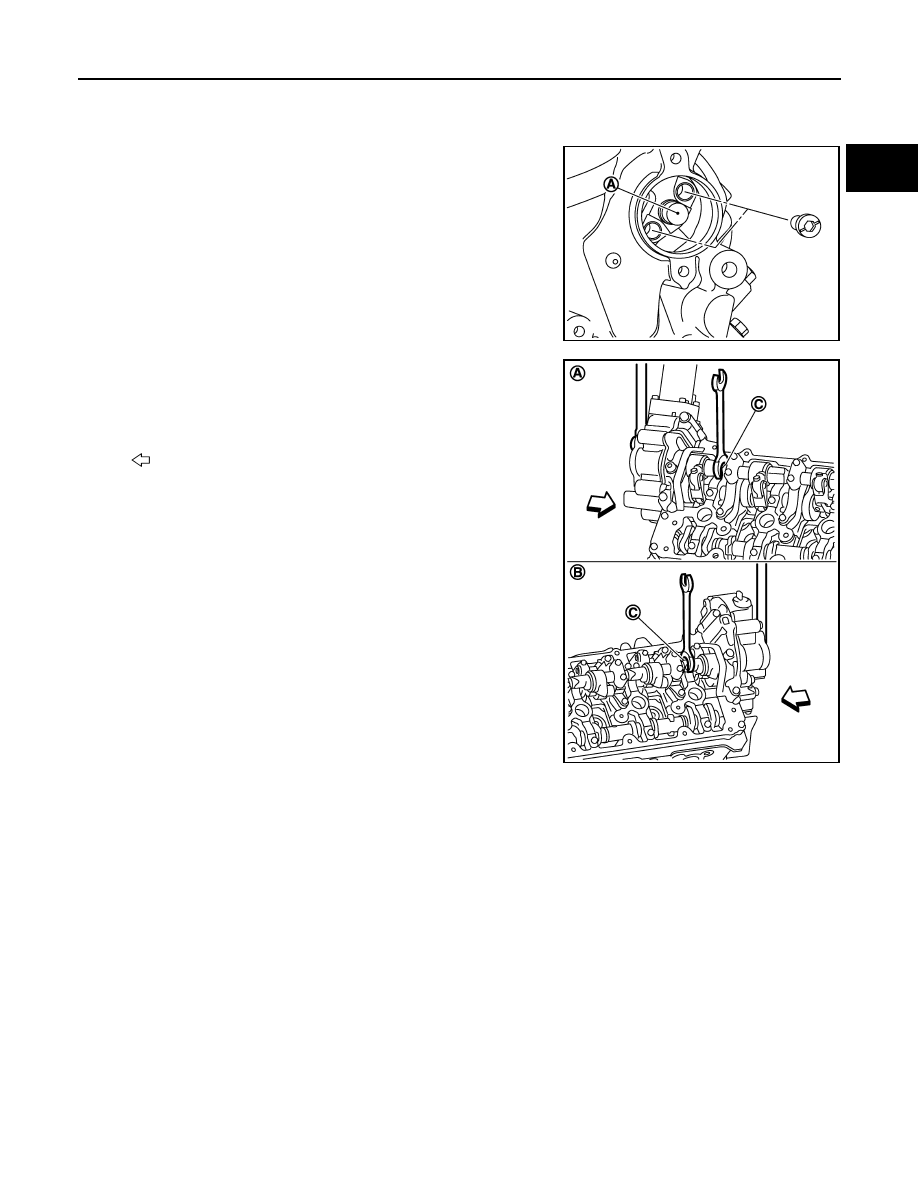
• Be sure to check that the VVEL actuator sub assembly is in contact with the cylinder head before
tightening the mounting bolts.
e.
Remove holding jig.
f.
Check that VVEL actuator arm bolt hole is aligned with control
shaft tapped hole. If it is not aligned, turn control shaft for align-
ment.
CAUTION:
Never give an impact to the magnet part. (A)
g.
Fix two flat areas (C) of control shaft with a wrench to tighten
mounting bolts of control shaft.
CAUTION:
• During the operation, never allow a wrench to interfere
with other parts.
• Fix control shaft to prevent the interference of the stopper
surface.
7.
Install new VVEL control shaft position sensor as per the following:
CAUTION:
Regarding replacement, because VVEL actuator sub assembly and VVEL control shaft position
sensor are controlled on a one-on-one basis, replace them as a set.
a.
Apply engine oil to O-ring or contact surface of O-ring.
JPBIA2141ZZ
A
: Bank 2
B
: Bank 1
: Engine front
JPBIA2143ZZ
Нет комментариевНе стесняйтесь поделиться с нами вашим ценным мнением.
Текст