Infiniti FX35, FX50 (S51). Manual — part 982
EM-228
< UNIT DISASSEMBLY AND ASSEMBLY >
[VK50VE]
CAMSHAFT
• VVEL ladder assembly cannot be replaced as a single part, because it is machined together with cylinder
head assembly.
VVEL Ladder Assembly & Cylinder Head Assembly Features
NOTE:
The figure shows an example of bank 1.
Disassembly and Assembly
INFOID:0000000005245254
DISASSEMBLY
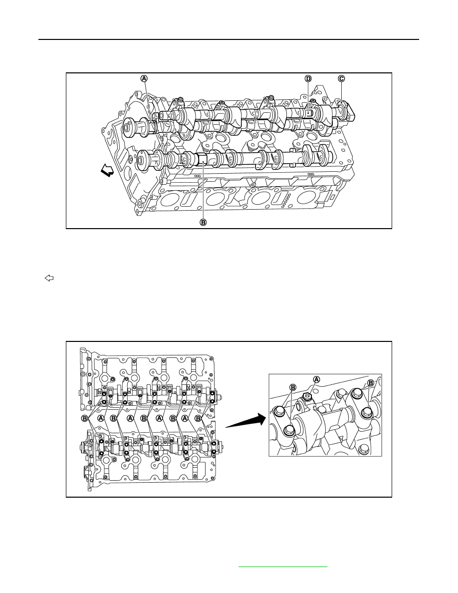
CAUTION:
Never loosen adjusting bolts (A) and mounting bolts (black color) (B) of VVEL ladder assembly. If loos-
ened, the stroke of cam lift becomes out of adjustment. In such case, replacement of VVEL ladder
assembly and cylinder head assembly is required.
NOTE:
VVEL ladder assembly cannot be replaced as a single part, because it is machined together with cylinder
head assembly.
1.
Remove rocker covers (bank 1 and bank 2). Refer to
.
JPBIA2123ZZ
A.
Hexagonal part of drive shaft
(for holding)
B.
Hexagonal part of camshaft (EXH)
(for holding)
C.
Stopper of control shaft
D.
Two flat areas of control shaft
(for holding)
: Engine front
JPBIA2126ZZ
CAMSHAFT
EM-229
< UNIT DISASSEMBLY AND ASSEMBLY >
[VK50VE]
C
D
E
F
G
H
I
J
K
L
M
A
EM
N
P
O
2.
Remove VVEL actuator sub assembly as per the following:
CAUTION:
VVEL actuator sub assembly and VVEL control shaft position sensor are not reusable. Never
remove them unless they are required.
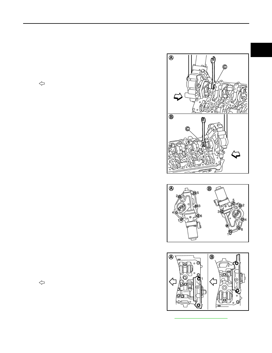
a.
Remove VVEL control shaft position sensor.
b.
Fix two flat areas (C) of control shaft with a wrench to remove
mounting bolts of control shaft.
CAUTION:
• During the operation, never allow a wrench to interfere
with other parts.
• Fix control shaft to prevent the interference of the stopper
surface.
c.
Remove VVEL actuator sub assembly.
• Loosen mounting bolts in the reverse order as shown in the
figure.
CAUTION:
• When removing, prepare wastes because oil spills.
• When installing, be careful with VVEL actuator sub
assembly (bank 1) mounting bolt No. 4 because its length
is different.
d.
Remove actuator bracket (rear).
• Loosen mounting bolts in the reverse order as shown in the
figure.
3.
Remove front cover, camshaft sprockets, and timing chains. Refer to
4.
Remove VVEL ladder assembly.
A
: Bank 2
B
: Bank 1
: Engine front
JPBIA2143ZZ
A
: Bank 1
B
: Bank 2
JPBIA2127ZZ
A
: Bank 2
B
: Bank 1
: Engine front
JPBIA2125ZZ
EM-230
< UNIT DISASSEMBLY AND ASSEMBLY >
[VK50VE]
CAMSHAFT
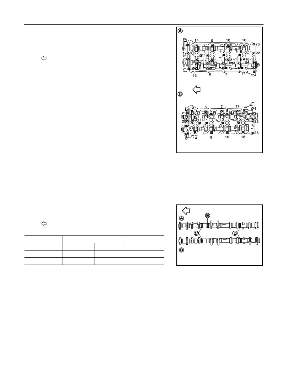
• Loosen mounting bolts (gold color) in the reverse order as
shown in the figure.
CAUTION:
• Never loosen adjusting bolts and mounting bolts (black
color).
• When removing VVEL ladder assembly, hold the drive
shaft from below so as not to drop it.
5.
Remove camshaft (EXH).
6.
Remove valve lifter, if necessary.
• Identify installation positions, and store them without mixing them up.
ASSEMBLY
1.
Install valve lifter.
• Install it in the original position.
2.
Install camshaft (EXH).
• Distinction between camshaft (EXH) is performed with the
identification mark.
3.
Install VVEL ladder assembly as per the following:
A
: Bank 2
B
: Bank 1
: Engine front
JPBIA2128ZZ
: Engine front
Bank
Paint marks
Identification rib (E)
M1 (C)
M2 (D)
Bank 2 (A)
No
Green
Yes
Bank 1 (B)
No
Green
No
JPBIA2130ZZ
CAMSHAFT
EM-231
< UNIT DISASSEMBLY AND ASSEMBLY >
[VK50VE]
C
D
E
F
G
H
I
J
K
L
M
A
EM
N
P
O
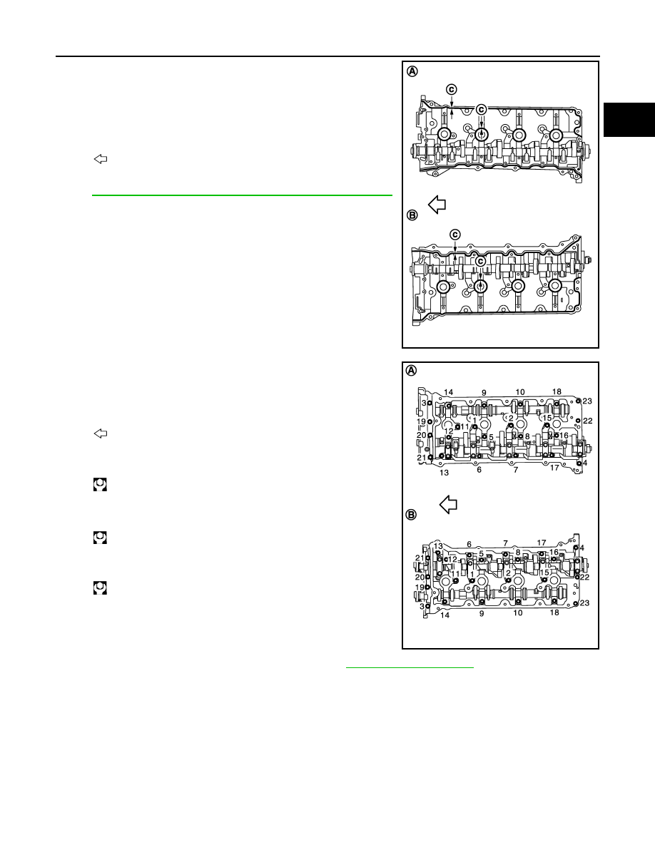
a.
Apply a continuous bead of liquid gasket with tube presser
(commercial service tool) to the cylinder head as shown in the
figure.
Use Genuine RTV Silicone Sealant or an equivalent. Refer
to
GI-16, "Recommended Chemical Products and Sealants"
b.
Tighten mounting bolts in the following step, in numerical order
as shown.
i.
Tighten bolts in numerical order as shown.
ii.
Tighten bolts in numerical order as shown.
iii.
Tighten bolts in numerical order as shown.
4.
Install camshaft sprockets and timing chains. Refer to
5.
Install actuator bracket (rear) as per the following:
A
: Bank 1
B
: Bank 2
c
:
φ
3.4 - 4.4 mm (0.134 - 0.173 in)
: Engine front
JPBIA2131ZZ
A
: Bank 2
B
: Bank 1
: Engine front
: 1.96 N·m (0.20 kg-m, 1 ft-lb)
: 5.88 N·m (0.60 kg-m, 4 ft-lb)
: 10.4 N·m (1.1 kg-m, 8 ft-lb)
JPBIA2128ZZ
Нет комментариевНе стесняйтесь поделиться с нами вашим ценным мнением.
Текст