Infiniti FX35, FX50 (S51). Manual — part 1212
INL-48
< DTC/CIRCUIT DIAGNOSIS >
PUDDLE LAMP CIRCUIT
Fixed at 12 V>>Replace the total illumination control unit.
Fixed at 0 V>>GO TO 2.
2.
CHECK THE SYMPTOM
Check that the lamp fixed to ON or OFF.
Fixed OFF>>GO TO 3.
Fixed ON>>GO TO 5.
3.
CHECK PUDDLE LAMP POWER SUPPLY
1.
Turn ignition switch OFF.
2.
Disconnect the door mirror connector.
3.
Turn ignition switch ON.
4.
Check voltage between the door mirror lamp harness connector and ground.
Is the measurement value normal?
YES
>> GO TO 4.
NO
>> Check the hospitality lighting power supply circuit 2. Refer to
.
4.
CHECK PUDDLE LAMP CONTROL CIRCUIT FOR OPEN
1.
Turn ignition switch OFF.
2.
Disconnect the total illumination control unit connector.
3.
Check continuity between the total illumination control unit harness connector and door mirror harness
connector.
Does continuity exist?
YES
>> Replace the puddle lamp.
NO
>> Repair the harnesses or connectors.
5.
CHECK PUDDLE LAMP CONTROL CIRCUIT FOR SHORT
1.
Turn ignition switch OFF.
2.
Disconnect the total illumination control unit and puddle lamp connector.
3.
Check continuity between the total illumination control unit harness connector and ground.
Does continuity exist?
YES
>> Repair the harnesses or connectors.
NO
>> Replace the total illumination control unit.
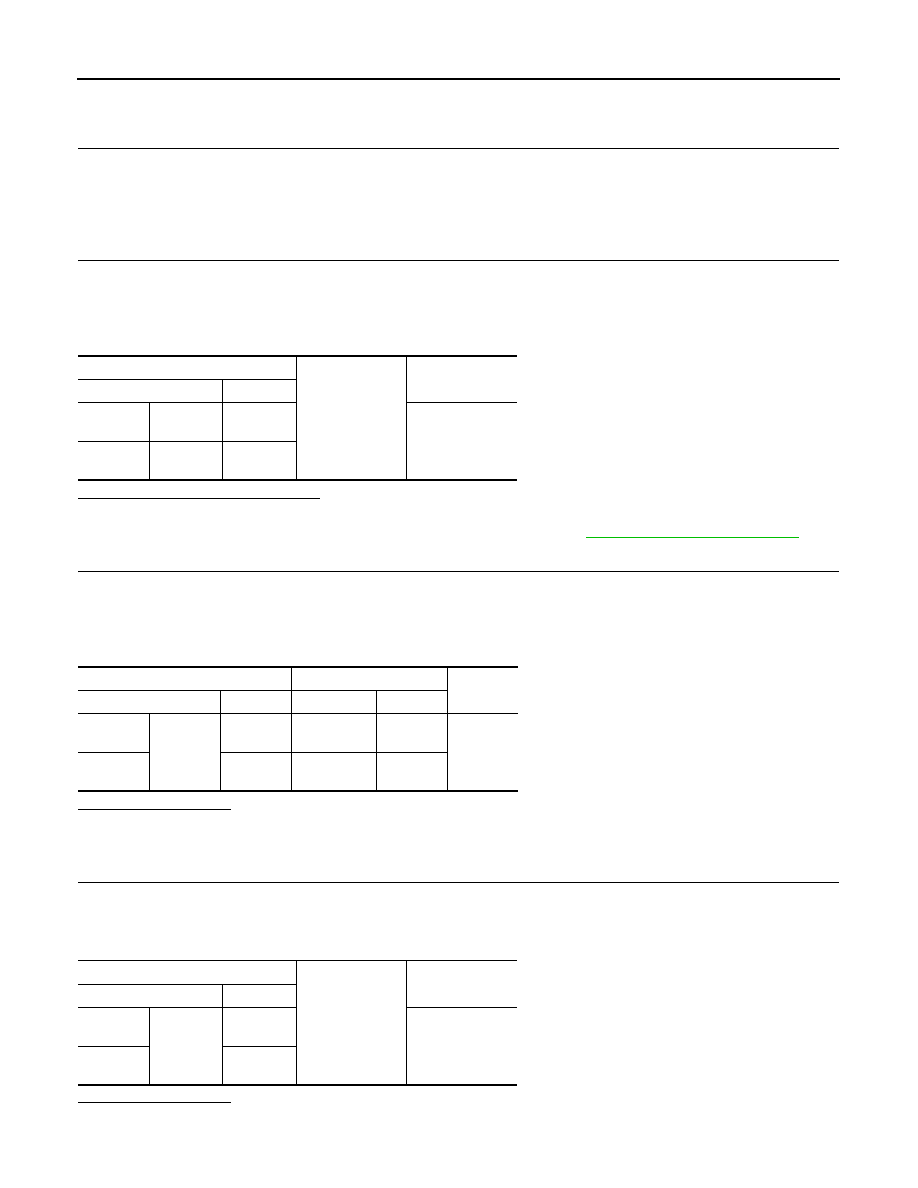
Door mirror
Ground
Voltage
(Approx.)
Connector
Terminal
Driver
side
D3
2
12 V
Passen-
ger side
D33
2
Total illumination control unit
Door mirror
Continuity
Connector
Terminal
Connector
Terminal
Driver
side
M129
40
D3
14
Existed
Passen-
ger side
39
D33
14
Total illumination control unit
Ground
Continuity
Connector
Terminal
Driver
side
M129
40
Not existed
Passen-
ger side
39
MOOD LAMP (FRONT DOOR ARMREST) CIRCUIT
INL-49
< DTC/CIRCUIT DIAGNOSIS >
C
D
E
F
G
H
I
J
K
M
A
B
INL
N
O
P
MOOD LAMP (FRONT DOOR ARMREST) CIRCUIT
Description
INFOID:0000000005245586
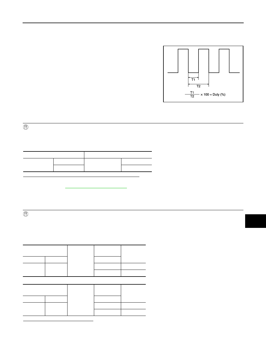
Controls the lamp (ground side) by PWM signal (duty).
Component Function Check
INFOID:0000000005245587
1.
CHECK MOOD LAMP (FRONT DOOR ARMREST) CONTROL FUNCTION
CONSULT-III ACTIVE TEST
1.
Turn ignition switch ON.
2.
Select “MOOD LAMP” of TOTAL ILLUM C/U active test item.
3.
While operating the test items, check mood lamp (front door armrest) operation.
Are the mood lamps (front door armrest) turned ON/OFF?
YES
>> Mood lamp (front door armrest) circuit is normal.
NO
>> Refer to
.
Diagnosis Procedure
INFOID:0000000005245588
1.
CHECK MOOD LAMP (FRONT DOOR ARMREST) CONTROL OUTPUT
CONSULT-III ACTIVE TEST
1.
Turn ignition switch ON.
2.
Select “MOOD LAMP” of TOTAL ILLUM C/U active test item.
3.
While operating the test items, check voltage between total illumination control unit harness connector
and ground.
Mood lamp (front door armrest RH)
Mood lamp (front door armrest LH)
Is the measurement value normal?
Fixed at 12 V>>Replace the total illumination control unit.
JPLIA1210GB
Test item
Operation
MOOD LAMP
On
Mood lamp
(front door armrest)
ON
Off
OFF
Total illumination control
unit
Ground
Test item
Voltage
(Approx.)
Connector
Terminal
MOOD LAMP
M129
10
On
0 V
Off
12 V
Total illumination control
unit
Ground
Test item
Voltage
(Approx.)
Connector
Terminal
MOOD LAMP
M129
30
On
0 V
Off
12 V
INL-50
< DTC/CIRCUIT DIAGNOSIS >
MOOD LAMP (FRONT DOOR ARMREST) CIRCUIT
Fixed at 0 V>>GO TO 2.
2.
CHECK THE SYMPTOM
Check that the lamp fixed to ON or OFF.
Fixed OFF>>GO TO 3.
Fixed ON>>GO TO 5.
3.
CHECK MOOD LAMP (FRONT DOOR ARMREST) POWER SUPPLY
1.
Turn ignition switch OFF.
2.
Disconnect the mood lamp (front door armrest) connector.
3.
Turn ignition switch ON.
4.
Check voltage between the mood lamp (front door armrest) harness connector and ground.
Is the measurement value normal?
YES
>> GO TO 4.
NO
>> Check the hospitality lighting power supply circuit 2. Refer to
.
4.
CHECK MOOD LAMP (FRONT DOOR ARMREST) CONTROL CIRCUIT FOR OPEN
1.
Turn ignition switch OFF.
2.
Disconnect the total illumination control unit connector.
3.
Check continuity between the total illumination control unit harness connector and mood lamp (front door
armrest) harness connector.
Does continuity exist?
YES
>> Replace the mood lamp (front door armrest).
NO
>> Repair the harnesses or connectors.
5.
CHECK MOOD LAMP (FRONT DOOR ARMREST) CONTROL CIRCUIT FOR SHORT
1.
Turn ignition switch OFF.
2.
Disconnect the total illumination control unit and mood lamp (front door armrest) connectors.
3.
Check continuity between the total illumination control unit harness connector and ground.
Does continuity exist?
YES
>> Repair the harnesses or connectors.
NO
>> Replace the total illumination control unit.
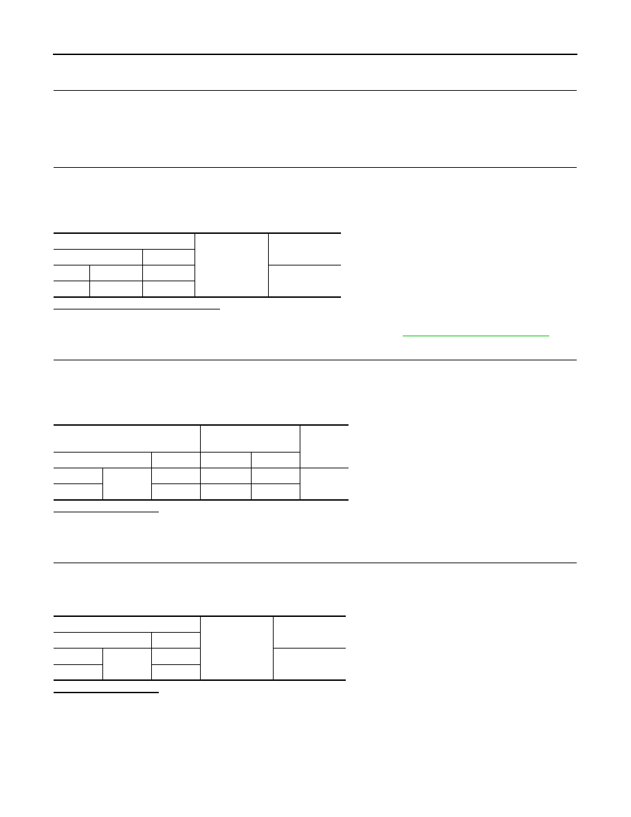
Mood lamp (front door armrest)
Ground
Voltage
(Approx.)
Connector
Terminal
RH
D46
1
12 V
LH
D16
1
Total illumination control unit
Mood lamp
(front door armrest)
Continuity
Connector
Terminal
Connector
Terminal
RH
M129
10
D46
2
Existed
LH
30
D16
2
Total illumination control unit
Ground
Continuity
Connector
Terminal
RH
M129
10
Not existed
LH
30

PUSH-BUTTON IGNITION SWITCH ILLUMINATION CIRCUIT
INL-51
< DTC/CIRCUIT DIAGNOSIS >
C
D
E
F
G
H
I
J
K
M
A
B
INL
N
O
P
PUSH-BUTTON IGNITION SWITCH ILLUMINATION CIRCUIT
Description
INFOID:0000000005245589
Controls the lamp (ground side) by PWM signal (duty).
Component Function Check
INFOID:0000000005245590
1.
CHECK PUSH-BUTTON IGNITION SWITCH ILLUMINATION OPERATION
CONSULT-III ACTIVE TEST
1.
Turn ignition switch ON.
2.
Select “ENGINE SWITCH ILLUMINATION” of TOTAL ILLUM C/U active test item.
3.
While operating the test items, check the push-button ignition switch illumination operation.
Is the push-button ignition switch illumination turned ON/OFF?
YES
>> Push-button ignition switch illumination circuit is normal.
NO
>> Refer to
.
Diagnosis Procedure
INFOID:0000000005245591
1.
CHECK PUSH-BUTTON IGNITION SWITCH ILLUMINATION CONTROL OUTPUT
CONSULT-III ACTIVE TEST
1.
Turn ignition switch ON.
2.
Select “ENGINE SWITCH ILLUMINATION” of TOTAL ILLUM C/U active test item.
3.
While operating the test items, check voltage between total illumination control unit harness connector
and ground.
Driver side
Is the measurement value normal?
Fixed at 12 V>>Replace the total illumination control unit.
Fixed at 0 V>>GO TO 2.
2.
CHECK THE SYMPTOM
Check that the lamp fixed to ON or OFF.
Fixed OFF>>GO TO 3.
JPLIA1210GB
Test item
Operation
ENGINE SWITCH IL-
LUMINATION
On
Push-button ignition
switch illumination
ON
Off
OFF
Total illumination control
unit
Ground
Test item
Voltage
(Approx.)
Connector
Terminal
ENGINE
SWITCH ILLU-
MINATION
M129
19
On
0 V
Off
12 V
Нет комментариевНе стесняйтесь поделиться с нами вашим ценным мнением.
Текст