Infiniti FX35, FX50 (S51). Manual — part 1210
INL-40
< DTC/CIRCUIT DIAGNOSIS >
PERSONAL LAMP CIRCUIT
PERSONAL LAMP CIRCUIT
Description
INFOID:0000000005245574
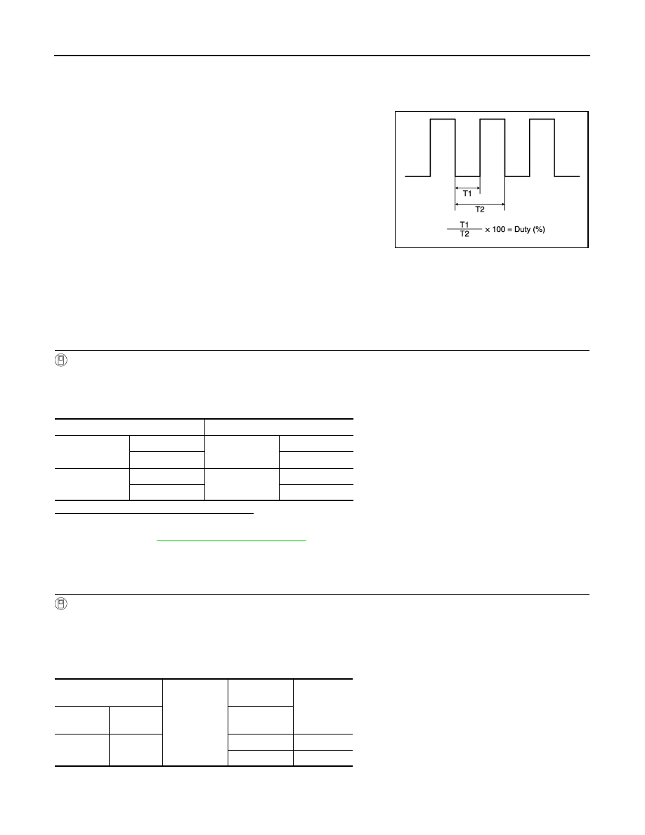
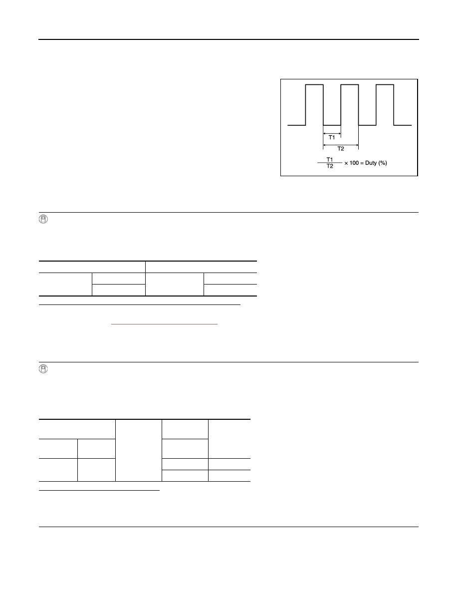
Controls the lamp (ground side) by PWM signal (duty) when map
lamp main switch is DOOR.
Component Function Check
INFOID:0000000005245575
CAUTION:
Before performing the diagnosis, check that the following items are normal.
• Hospitality lighting power supply 1 circuit (When both sides lamp are not turned ON.)
• Personal lamp bulbs
1.
CHECK PERSONAL LAMP CONTROL FUNCTION
CONSULT-III ACTIVE TEST
1.
Turn ignition switch ON.
2.
Select “PERSONAL LAMP-RR” or “PERSONAL LAMP-RL” of TOTAL ILLUM C/U active test item.
3.
While operating the test items, check personal lamps operation.
Are the personal lamps turned ON/OFF?
YES
>> Personal lamp circuit is normal.
NO
>> Refer to
.
Diagnosis Procedure
INFOID:0000000005245576
1.
CHECK PERSONAL LAMP CONTROL OUTPUT
CONSULT-III ACTIVE TEST
1.
Turn ignition switch ON.
2.
Select “PERSONAL LAMP-RR” or “PERSONAL LAMP-RR” of TOTAL ILLUM C/U active test item.
3.
While operating the test items, check voltage between total illumination control unit harness connector
and ground.
Personal lamp RH
JPLIA1210GB
Test item
Operation
PERSONAL
LAMP-RR
On
Personal lamp
(RH)
ON
Off
OFF
PERSONAL
LAMP-RL
On
Personal lamp
(LH)
ON
Off
OFF
Total illumination control
unit
Ground
Test item
Voltage
(Approx.)
Connector
Terminal
PERSONAL
LAMP-RR
M129
14
On
0 V
Off
12 V
PERSONAL LAMP CIRCUIT
INL-41
< DTC/CIRCUIT DIAGNOSIS >
C
D
E
F
G
H
I
J
K
M
A
B
INL
N
O
P
Personal lamp LH
Is the measurement value normal?
Fixed at 12 V>>Replace the total illumination control unit.
Fixed at 0 V>>GO TO 2.
2.
CHECK THE SYMPTOM
Check that the lamp fixed to ON or OFF.
Fixed OFF>>GO TO 3.
Fixed ON>>GO TO 4.
3.
CHECK PERSONAL LAMP CONTROL CIRCUIT FOR OPEN
1.
Turn ignition switch OFF.
2.
Disconnect the total illumination control unit and personal lamp connectors.
3.
Check continuity between the total illumination control unit harness connector and personal lamp harness
connector.
Does continuity exist?
YES
>> Replace the personal lamp assembly.
NO
>> Repair the harnesses or connectors.
4.
CHECK PERSONAL LAMP CONTROL CIRCUIT FOR SHORT
1.
Turn ignition switch OFF.
2.
Disconnect the total illumination control unit and personal lamp connectors.
3.
Check continuity between the total illumination control unit harness connector and ground.
Does continuity exist?
YES
>> Repair the harnesses or connectors.
NO
>> Replace the total illumination control unit.
Total illumination control
unit
Ground
Test item
Voltage
(Approx.)
Connector
Terminal
PERSONAL
LAMP-RL
M129
13
On
0 V
Off
12 V
Total illumination control unit
Personal lamp
Continuity
Connector
Terminal
Connec-
tor
Terminal
RH
M129
14
R14
3
Existed
LH
13
1
Total illumination control unit
Ground
Continuity
Connector
Terminal
RH
M129
14
Not existed
LH
13
INL-42
< DTC/CIRCUIT DIAGNOSIS >
CENTER CONSOLE INDIRECT ILLUMINATION CIRCUIT
CENTER CONSOLE INDIRECT ILLUMINATION CIRCUIT
Description
INFOID:0000000005245577
Controls the lamp (ground side) by PWM signal (duty).
Component Function Check
INFOID:0000000005245578
1.
CHECK CENTER CONSOLE INDIRECT ILLUMINATION CONTROL FUNCTION
CONSULT-III ACTIVE TEST
1.
Turn ignition switch ON.
2.
Select “AMBIENCE LAMP” of TOTAL ILLUM C/U active test item.
3.
While operating the test items, check center console indirect illumination operation.
Is the center console indirect illumination turned ON/OFF?
YES
>> Center console indirect illumination circuit is normal.
NO
>> Refer to
.
Diagnosis Procedure
INFOID:0000000005245579
1.
CHECK CENTER CONSOLE INDIRECT ILLUMINATION CONTROL OUTPUT
CONSULT-III ACTIVE TEST
1.
Turn ignition switch ON.
2.
Select “AMBIENCE LAMP” of TOTAL ILLUM C/U active test item.
3.
While operating the test items, check voltage between total illumination control unit harness connector
and ground.
Is the measurement value normal?
Fixed at 12 V>>Replace the total illumination control unit.
Fixed at 0 V>>GO TO 2.
2.
CHECK THE SYMPTOM
Check that the lamp fixed to ON or OFF.
Fixed OFF>>GO TO 3.
Fixed ON>>GO TO 5.
JPLIA1210GB
Test item
Operation
AMBIENCE
LAMP
On
Center console in-
direct illumination
ON
Off
OFF
Total illumination control
unit
Ground
Test item
Voltage
(Approx.)
Connector
Terminal
AMBIENCE
LAMP
M129
20
On
0 V
Off
12 V
CENTER CONSOLE INDIRECT ILLUMINATION CIRCUIT
INL-43
< DTC/CIRCUIT DIAGNOSIS >
C
D
E
F
G
H
I
J
K
M
A
B
INL
N
O
P
3.
CHECK CENTER CONSOLE INDIRECT ILLUMINATION POWER SUPPLY
1.
Turn ignition switch OFF.
2.
Disconnect the map lamp connector.
3.
Turn ignition switch ON.
4.
Check voltage between the map lamp harness connector and ground.
Is the measurement value normal?
YES
>> GO TO 4.
NO
>> Check the hospitality lighting power supply circuit 1. Refer to
4.
CHECK CENTER CONSOLE INDIRECT ILLUMINATION CONTROL CIRCUIT FOR OPEN
1.
Turn ignition switch OFF.
2.
Disconnect the total illumination control unit connector.
3.
Check continuity between the total illumination control unit harness connector and map lamp harness con-
nector.
Does continuity exist?
YES
>> Replace the map lamp assembly.
NO
>> Repair the harnesses or connectors.
5.
CHECK CENTER CONSOLE INDIRECT ILLUMINATION CONTROL CIRCUIT FOR SHORT
1.
Turn ignition switch OFF.
2.
Disconnect the total illumination control unit and map lamp connectors.
3.
Check continuity between the total illumination control unit harness connector and ground.
Does continuity exist?
YES
>> Repair the harnesses or connectors.
NO
>> Replace the total illumination control unit.
Map lamp
Ground
Voltage
(Approx.)
Connector
Terminal
R15
5
12 V
Total illumination control unit
Map lamp
Continuity
Terminal
Connector
Terminal
M129
20
R15
6
Existed
Total illumination control unit
Ground
Continuity
Connector
Terminal
Not existed
M129
20
Нет комментариевНе стесняйтесь поделиться с нами вашим ценным мнением.
Текст