Infiniti FX35, FX50 (S51). Manual — part 109
AV
AROUND VIEW MONITOR CONTROL UNIT
AV-209
< ECU DIAGNOSIS INFORMATION >
[NAVIGATION (SINGLE MONITOR)]
C
D
E
F
G
H
I
J
K
L
M
B
A
O
P
36
(G)
Ground
Rear camera power supply
Output
Ignition
switch
ON
“CAMERA” switch is ON or
shift position is “R”.
6.0 V
37
—
Shield
—
—
—
—
38
(L)
Ground
Rear camera ground
—
Ignition
switch
ON
—
0 V
39
(Y)
40
(BR)
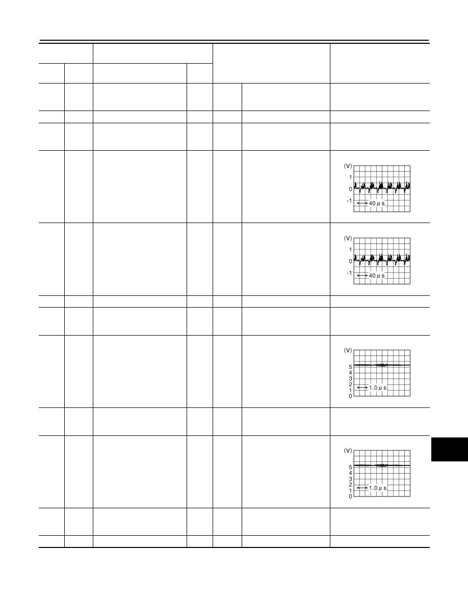
Rear camera image signal
Input
Ignition
switch
ON
“CAMERA” switch is ON or
shift position is “R”.
41
(L)
42
(BR)
Front camera image signal
Input
Ignition
switch
ON
“CAMERA” switch is ON or
shift position is “R”.
43
—
Shield
—
—
—
—
44
(Y)
Ground
Front camera ground
—
Ignition
switch
ON
—
0 V
45
(W)
Ground
Front camera communication
signal
Input/
Output
Ignition
switch
ON
“CAMERA” switch is ON or
shift position is “R”.
46
(G)
Ground
Front camera power supply
Output
Ignition
switch
ON
“CAMERA” switch is ON or
shift position is “R”.
6.0 V
47
(BR)
Ground
Side camera driver side com-
munication signal
Input/
Output
Ignition
switch
ON
“CAMERA” switch is ON or
shift position is “R”.
48
(L)
Ground
Side camera driver side power
supply
Output
Ignition
switch
ON
“CAMERA” switch is ON or
shift position is “R”.
6.0 V
49
—
Shield
—
—
—
—
Terminal
(Wire color)
Description
Condition
Reference value
(Approx.)
+
–
Signal name
Input/
Output
JSNIA0834GB
JSNIA0834GB
JSNIA0836GB
JSNIA0836GB
AV-210
< ECU DIAGNOSIS INFORMATION >
[NAVIGATION (SINGLE MONITOR)]
AROUND VIEW MONITOR CONTROL UNIT
50
(W)
Ground
Side camera driver side
ground
—
Ignition
switch
ON
—
0 V
51
(R)
52
(Y)
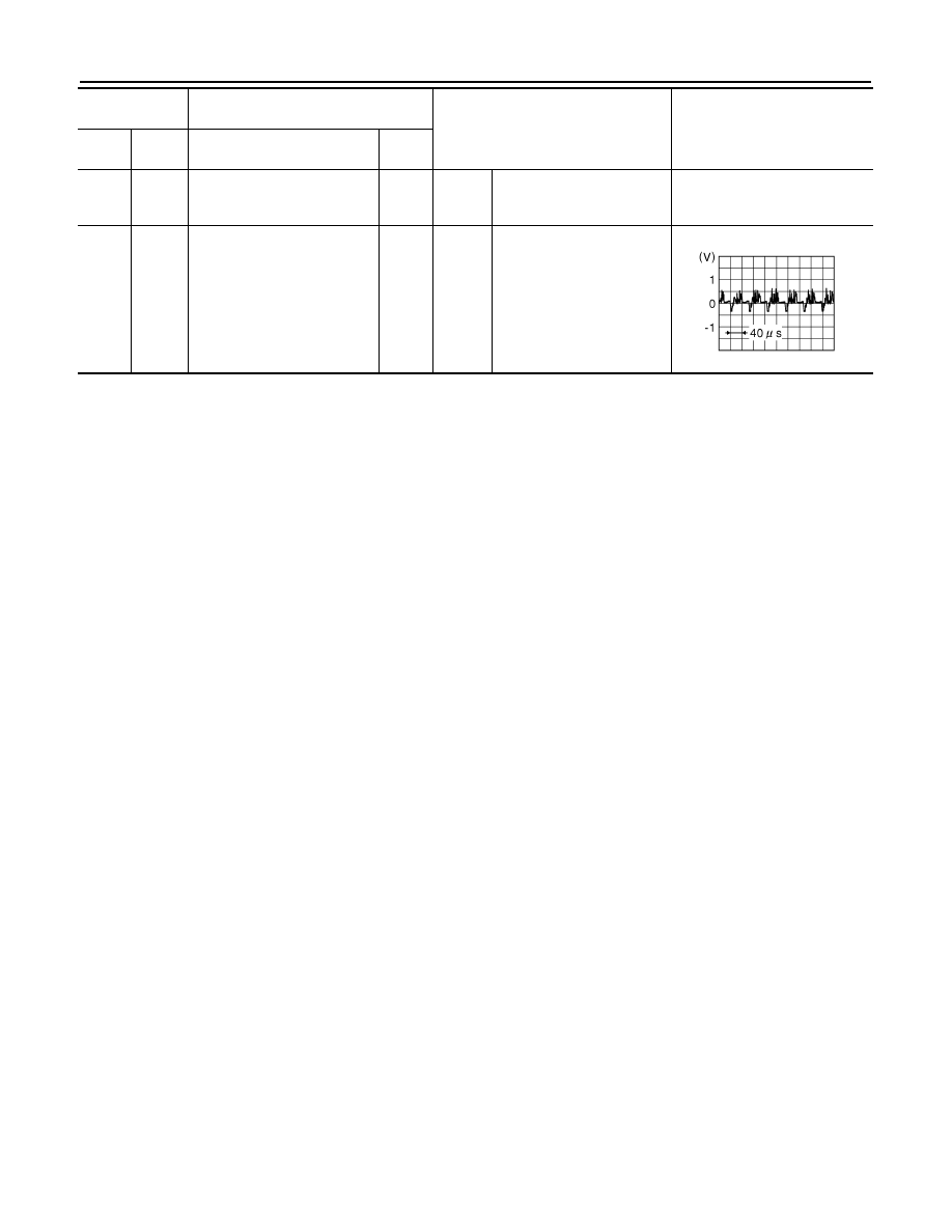
Side camera driver side image
signal
Input
Ignition
switch
ON
“CAMERA” switch is ON or
shift position is “R”.
Terminal
(Wire color)
Description
Condition
Reference value
(Approx.)
+
–
Signal name
Input/
Output
JSNIA0834GB

AV
SONAR CONTROL UNIT (WITH AROUND VIEW MONITOR)
AV-211
< ECU DIAGNOSIS INFORMATION >
[NAVIGATION (SINGLE MONITOR)]
C
D
E
F
G
H
I
J
K
L
M
B
A
O
P
SONAR CONTROL UNIT (WITH AROUND VIEW MONITOR)
Reference Value
INFOID:0000000005475081
VALUES ON THE DIAGNOSIS TOOL
CONSULT-III MONITOR ITEM
Monitor Item
Condition
Value/Status
SONAR OPE
Ignition switch
ON
Around view monitor operating (sonar operating).
On
Around view monitor non-operating (sonar non-operat-
ing).
Off
BUZZER OUTPUT
Ignition switch
ON
Buzzer is output condition.
On
Buzzer is not output condition.
Off
CR SEN [FL]
Ignition switch
ON
When a sensor is abnormal.
ERROR
When a sensor is not detection.
LV.0
The distance between the corner sensor and an obstacle
is 60 cm (23.6 in) or more and less then 70 cm (27.5 in).
LV.2
The distance between the corner sensor and an obstacle
is 40 cm (15.7 in) or more and less then 60 cm (23.6 in).
LV.3
The distance between corner sensor and an obstacle
less than 40 cm (15.7 in).
LV.4
CR SEN [FR]
Ignition switch
ON
When a sensor is abnormal.
ERROR
When a sensor is not detection.
LV.0
The distance between the corner sensor and an obstacle
is 60 cm (23.6 in) or more and less then 70 cm (27.5 in).
LV.2
The distance between the corner sensor and an obstacle
is 40 cm (15.7 in) or more and less then 60 cm (23.6 in).
LV.3
The distance between corner sensor and an obstacle
less than 40 cm (15.7 in).
LV.4
CR SEN [RL]
Ignition switch
ON
When a sensor is abnormal.
ERROR
When a sensor is not detection.
LV.0
The distance between the corner sensor and an obstacle
is 60 cm (23.6 in) or more and less then 70 cm (27.5 in).
LV.2
The distance between the corner sensor and an obstacle
is 40 cm (15.7 in) or more and less then 60 cm (23.6 in).
LV.3
The distance between corner sensor and an obstacle
less than 40 cm (15.7 in).
LV.4
CR SEN [RR]
Ignition switch
ON
When a sensor is abnormal.
ERROR
When a sensor is not detection.
LV.0
The distance between the corner sensor and an obstacle
is 60 cm (23.6 in) or more and less then 70 cm (27.5 in).
LV.2
The distance between the corner sensor and an obstacle
is 40 cm (15.7 in) or more and less then 60 cm (23.6 in).
LV.3
The distance between corner sensor and an obstacle
less than 40 cm (15.7 in).
LV.4
AV-212
< ECU DIAGNOSIS INFORMATION >
[NAVIGATION (SINGLE MONITOR)]
SONAR CONTROL UNIT (WITH AROUND VIEW MONITOR)
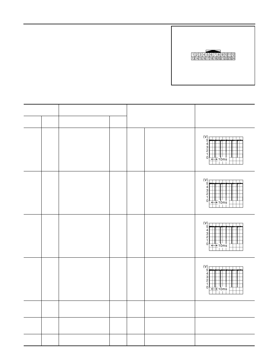
TERMINAL LAYOUT
PHYSICAL VALUES
JSNIA0303ZZ
Terminal No.
(Wire color)
Description
Condition
Value
(Approx.)
+
–
Signal name
Input/
Output
3
(W)
12
(B)
Corner sensor signal front
LH
Input
Ignition
switch
ON
“CAMERA” switch is ON or
shift position is “R”.
4
(R)
12
(B)
Corner sensor signal front
RH
Input
Ignition
switch
ON
“CAMERA” switch is ON or
shift position is “R”.
5
(W)
12
(B)
Corner sensor signal rear
LH
Input
Ignition
switch
ON
“CAMERA” switch is ON or
shift position is “R”.
6
(R)
12
(B)
Corner sensor signal rear
RH
Input
Ignition
switch
ON
“CAMERA” switch is ON or
shift position is “R”.
12
(B)
Ground
Sensor ground
—
Ignition
switch
ON
—
0 V
13
(V)
Ground
ACC power supply
Input
Ignition
switch
ACC
—
12.0 V
18
(P)
—
K-line (CONSULT-III)
—
—
—
—
JSNIA0837GB
JSNIA0837GB
JSNIA0837GB
JSNIA0837GB
Нет комментариевНе стесняйтесь поделиться с нами вашим ценным мнением.
Текст