Infiniti FX35, FX50 (S51). Manual — part 1197
GAS SENSOR
HAC-185
< REMOVAL AND INSTALLATION >
[AUTOMATIC AIR CONDITIONER]
C
D
E
F
G
H
J
K
L
M
A
B
HAC
N
O
P
GAS SENSOR
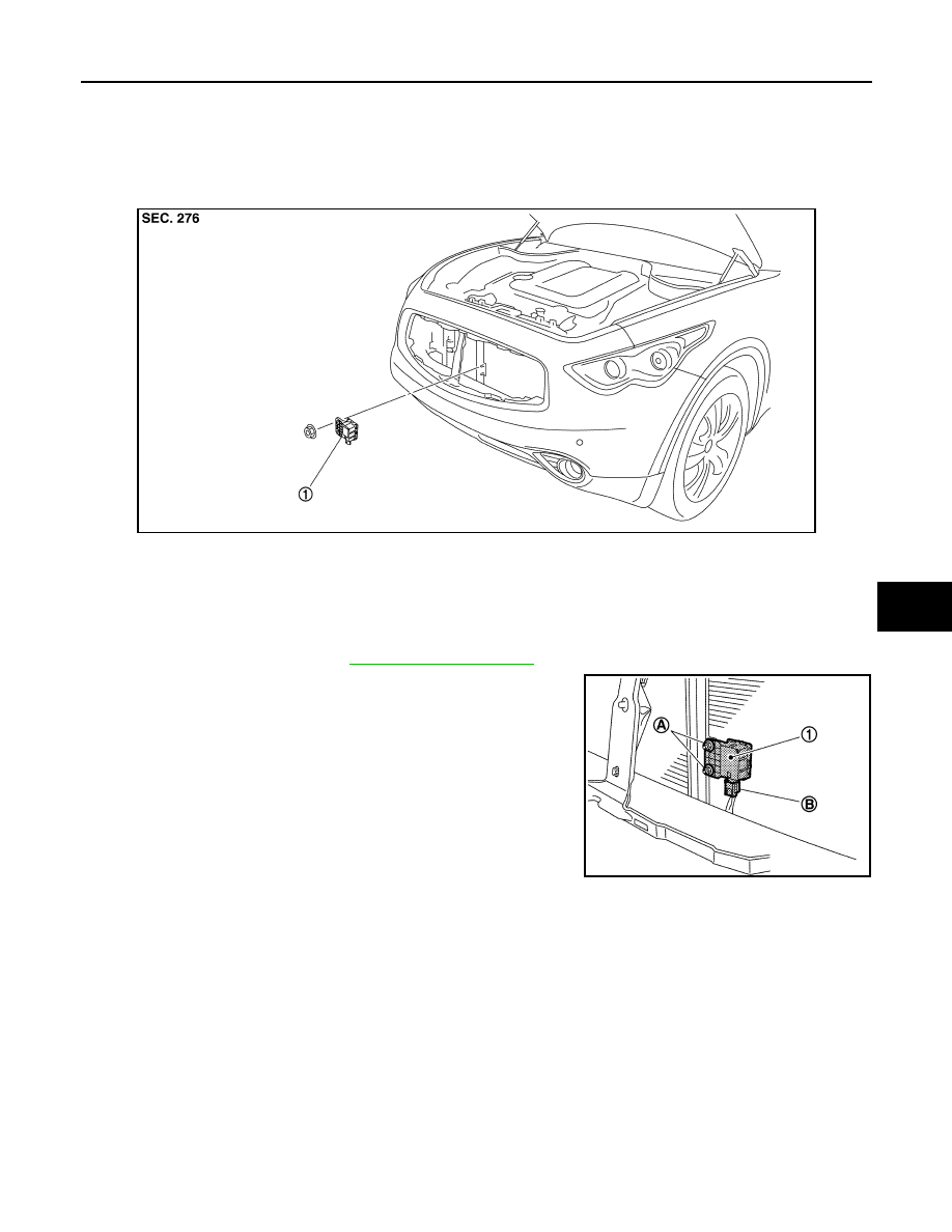
Exploded View
INFOID:0000000005246339
Removal and Installation
INFOID:0000000005246340
REMOVAL
1.
Remove air duct (inlet). Refer to
.
2.
Remove mounting nuts (A), and then remove gas sensor (1).
3.
Disconnect gas sensor connector (B).
INSTALLATION
Installation is basically the reverse order of removal.
JSIIA1300ZZ
1.
Gas sensor
JSIIA1301ZZ
HAC-186
< REMOVAL AND INSTALLATION >
[AUTOMATIC AIR CONDITIONER]
REFRIGERANT PRESSURE SENSOR
REFRIGERANT PRESSURE SENSOR
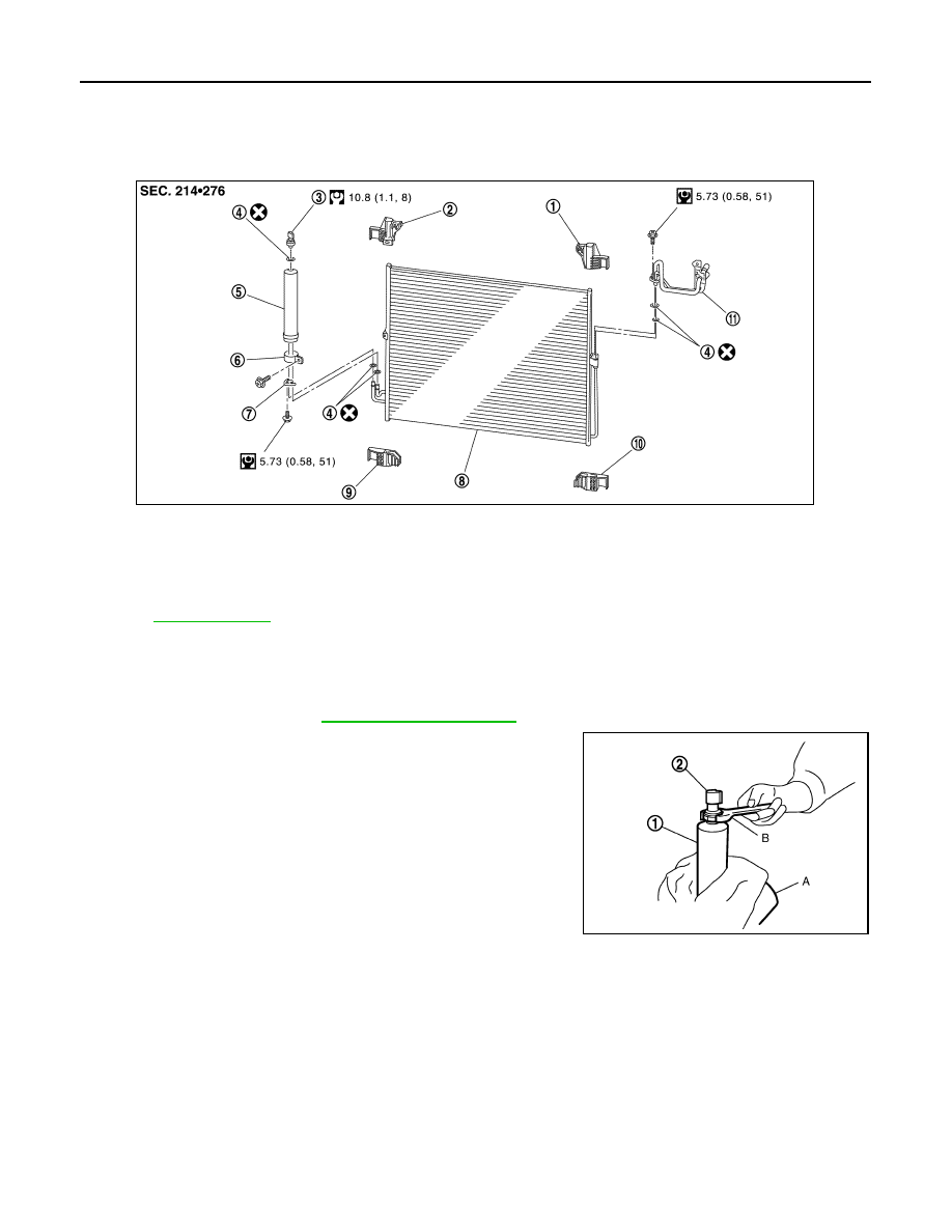
Exploded View
INFOID:0000000005246341
Removal and Installation
INFOID:0000000005246342
REMOVAL
1.
Remove liquid tank. Refer to
.
2.
Fix the liquid tank (1) with a vise (A). Remove the refrigerant
pressure sensor (2) with a wrench (B).
CAUTION:
Be careful not to damage liquid tank.
INSTALLATION
Installation is basically the reverse order of removal.
CAUTION:
• Replace O-ring with new one. Then apply compressor oil to them when installing.
• Check for leakages when recharging refrigerant.
1.
Condenser upper bracket (left)
2.
Condenser upper bracket (right)
3.
Refrigerant pressure sensor
4.
O-ring
5.
Liquid tank
6.
Liquid tank bracket
7.
Bracket
8.
Condenser
9.
Condenser lower bracket (right)
10. Condenser lower bracket (left)
11.
Condenser pipe assembly
Refer to
for symbols in the figure.
JSIIA1373GB
JSIIA0075ZZ
DOOR MOTOR
HAC-187
< REMOVAL AND INSTALLATION >
[AUTOMATIC AIR CONDITIONER]
C
D
E
F
G
H
J
K
L
M
A
B
HAC
N
O
P
DOOR MOTOR
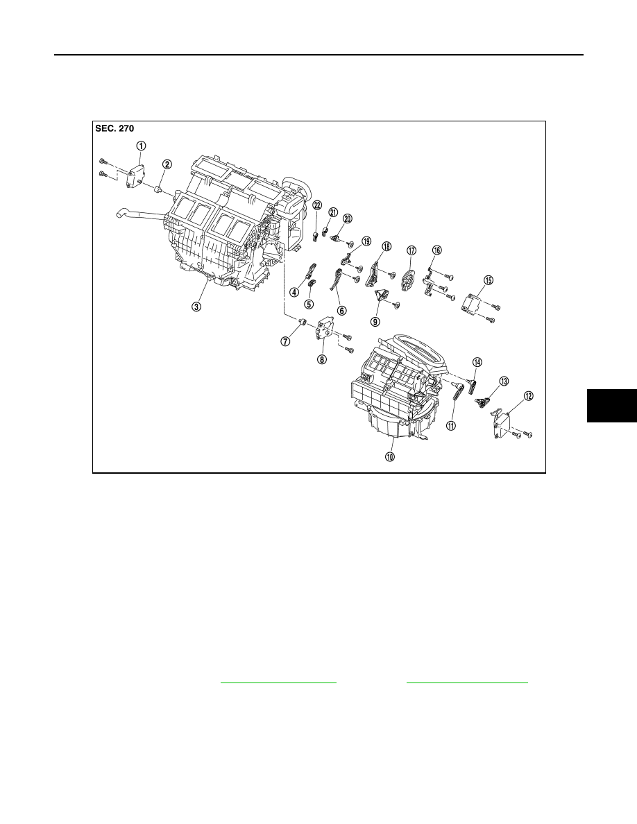
Exploded View
INFOID:0000000005246343
MODE DOOR MOTOR
MODE DOOR MOTOR : Removal and Installation
INFOID:0000000005246344
REMOVAL
1.
Remove blower unit. Refer to
(VQ35HR) or
(VK50VE).
1.
Air mix door motor (driver side)
2.
Air mix door motor adapter
3.
Heater & cooling unit assembly
4.
Ventilator door lever
5.
Foot door lever
6.
Foot door link
7.
Air mix door motor adapter
8.
Air mix door motor (passenger side) 9.
Ventilator door link
10. Blower unit
11.
Intake door lever 2
12. Intake door motor
13. Intake door link
14.
Intake door lever 1
15. Mode door motor
16. Mode door motor bracket
17.
Main link
18. Main link sub
19. Max.cool door link
20.
Defroster door link
21. Max.cool door lever
22. Defroster door lever
JPIIA0654ZZ
HAC-188
< REMOVAL AND INSTALLATION >
[AUTOMATIC AIR CONDITIONER]
DOOR MOTOR
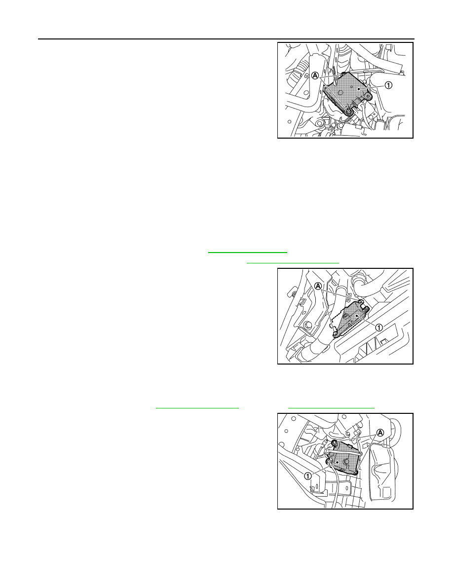
2.
Remove mounting screws (A), and then remove mode door
motor (1).
3.
Disconnect mode door motor connector.
INSTALLATION
installation is basically the reverse order of removal.
AIR MIX DOOR MOTOR
AIR MIX DOOR MOTOR : Removal and Installation
INFOID:0000000005246345
REMOVAL
Driver Side
1.
Set the temperature (driver side) at 18.0
°
C (60
°
F).
2.
Disconnect the battery cable from the negative terminal.
3.
Remove instrument lower panel LH. Refer to
4.
Remove automatic drive positioner control unit. Refer to
5.
Remove mounting screws (A), and then remove air mix door
motor (driver side) (1).
6.
Disconnect air mix door motor connector.
Passenger Side
1.
Set the temperature (passenger side) at 18
°
C (60
°
F).
2.
Disconnect the battery cable from the negative terminal.
3.
Remove blower unit. Refer to
(VQ35HR) or
(VK50VE).
4.
Remove mounting screws (A), and then remove air mix door
motor (passenger side) (1).
5.
Disconnect air mix door motor connector.
INSTALLATION
Installation is basically the reverse order of removal.
INTAKE DOOR MOTOR
JPIIA0664ZZ
JSIIA1311ZZ
JSIIA1312ZZ
Нет комментариевНе стесняйтесь поделиться с нами вашим ценным мнением.
Текст