Infiniti FX35, FX50 (S51). Manual — part 1196
IN-VEHICLE SENSOR
HAC-181
< REMOVAL AND INSTALLATION >
[AUTOMATIC AIR CONDITIONER]
C
D
E
F
G
H
J
K
L
M
A
B
HAC
N
O
P
IN-VEHICLE SENSOR
Exploded View
INFOID:0000000005246333
Removal and Installation
INFOID:0000000005246334
REMOVAL
1.
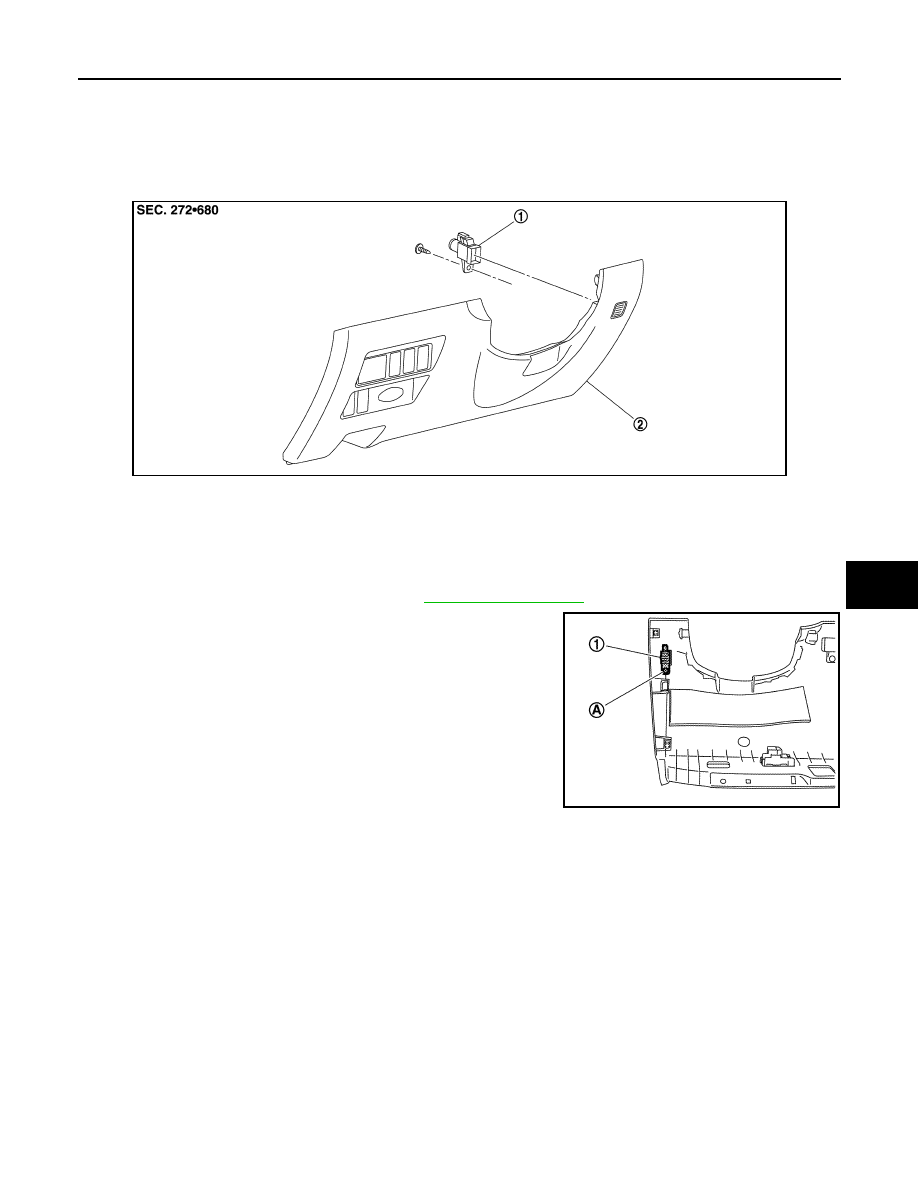
Remove instrument lower panel LH. Refer to
2.
Remove mounting screw (A), and then remove in-vehicle sensor
(1).
INSTALLATION
Installation is basically the reverse order of removal.
JSIIA1297ZZ
1.
In-vehicle sensor
2.
Instrument lower panel LH
JSIIA1298ZZ
HAC-182
< REMOVAL AND INSTALLATION >
[AUTOMATIC AIR CONDITIONER]
SUNLOAD SENSOR
SUNLOAD SENSOR
Exploded View
INFOID:0000000005246335
Removal and Installation
INFOID:0000000005246336
REMOVAL
1.
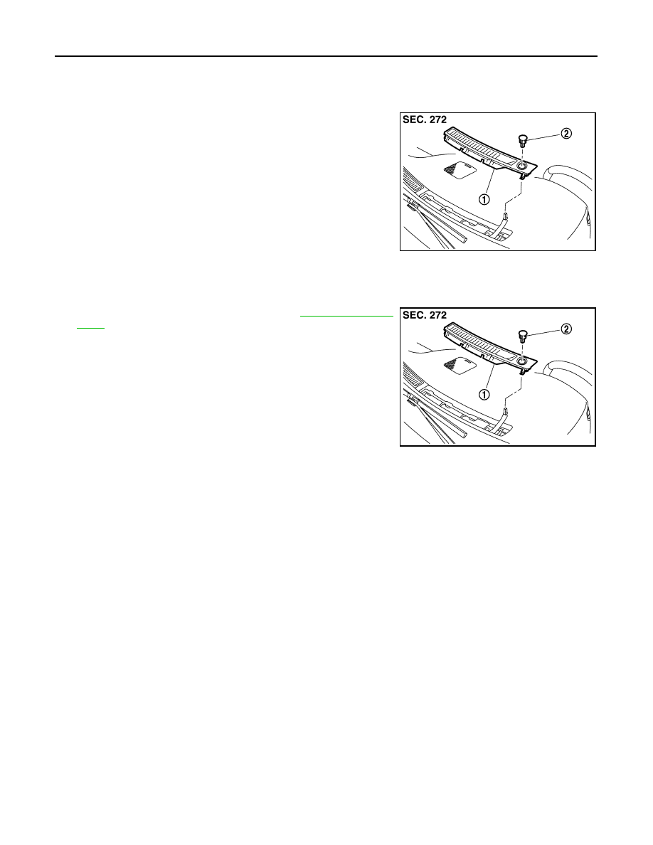
Remove front defroster grille LH (1). Refer to
.
2.
Disconnect sunload sensor connector, and then remove sunload
sensor (2).
INSTALLATION
Installation is basically the reverse order of removal.
1.
Front defroster grille LH
2.
Sunload sensor
JSIIA1299ZZ
JSIIA1299ZZ
INTAKE SENSOR
HAC-183
< REMOVAL AND INSTALLATION >
[AUTOMATIC AIR CONDITIONER]
C
D
E
F
G
H
J
K
L
M
A
B
HAC
N
O
P
INTAKE SENSOR
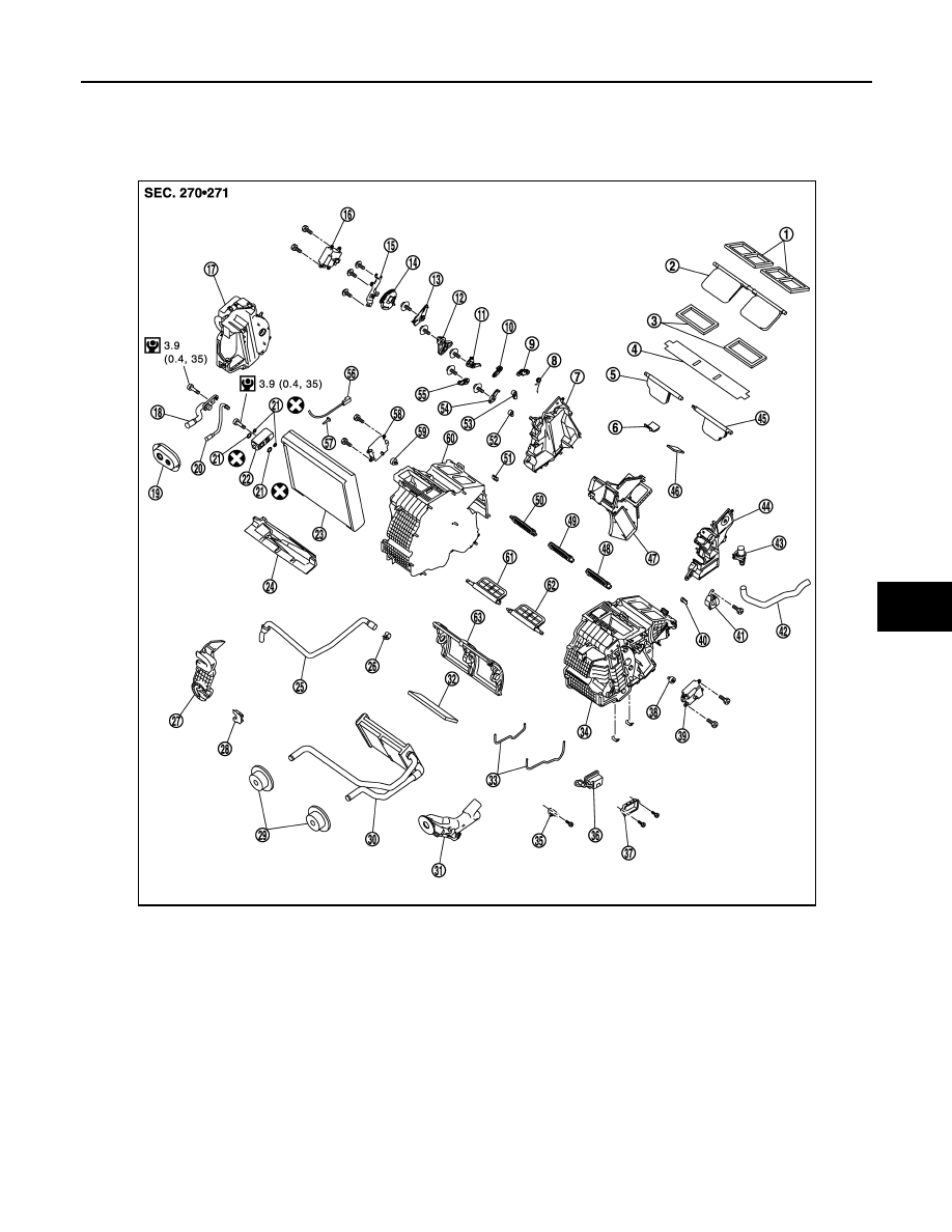
Exploded View
INFOID:0000000005246337
1.
Ventilator seal
2.
Ventilator door
3.
Defroster seal
4.
Packing
5.
Defroster door (right)
6.
Packing
7.
Foot duct (right)
8.
Ventilator door spring
9.
Ventilator door lever
10.
Foot door lever
11.
Foot door link
12. Main link sub
13.
Ventilator door link
14.
Main link
15. Mode door motor bracket
16.
Mode door motor
17.
Evaporator cover
18. Low-pressure pipe 1
19.
Cooler pipe grommet
20.
High-pressure pipe 2
21. O-ring
22.
Expansion valve
23.
Evaporator
24. Insulator
25.
Drain hose
26.
Clamp
27. Evaporator cover adapter
28.
Heater pipe bracket
29.
Heater pipe grommet
30. Heater core
31.
Heater pipe cover
32.
Packing
33. Case packing
34.
Heater & cooling unit case (left)
35.
Ionizer harness bracket
*
36. Ionizer
*
JSIIA1137GB
HAC-184
< REMOVAL AND INSTALLATION >
[AUTOMATIC AIR CONDITIONER]
INTAKE SENSOR
Removal and Installation
INFOID:0000000005246338
REMOVAL
1.
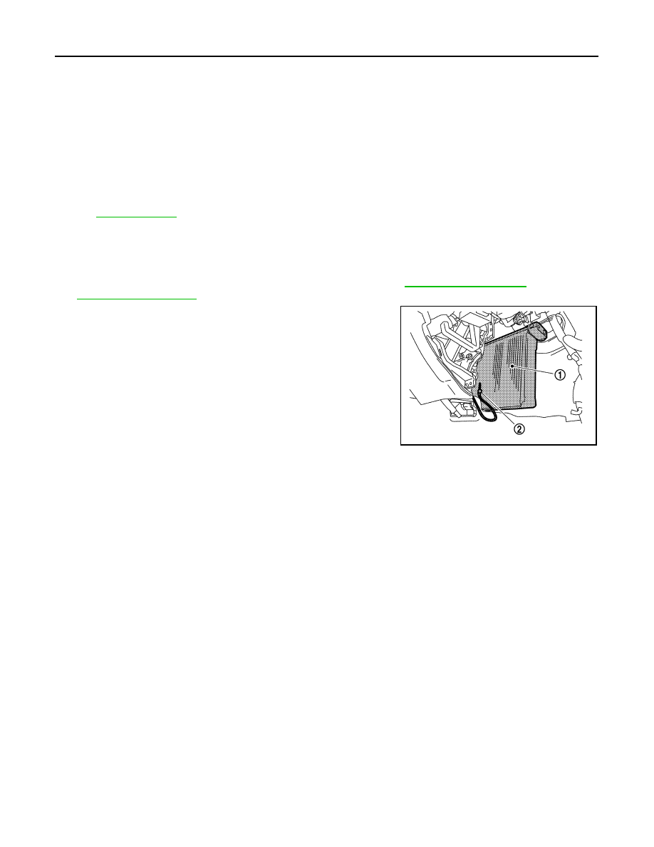
Remove low-pressure pipe 1 and high-pressure pipe 2. Refer to
(VQ35HR) or
2.
Slide evaporator (1) to passenger side, and then remove intake
sensor (2).
3.
Disconnect intake sensor connector.
INSTALLATION
Installation is basically the reverse order of removal.
CAUTION:
• Replace O-rings with new ones. Then apply compressor oil to them when installing.
• Mark the mounting position of intake sensor bracket prior to removal so that the reinstalled sensor
can be located in the same position.
• Female-side piping connection is thin and easy to deform. Slowly insert the male-side piping
straight in axial direction.
• Insert piping securely until a click is heard.
• After piping connection is completed, pull male-side piping by hand to make sure that connection
does not come loose.
• Check for leakages when recharging refrigerant.
37. Ionizer bracket
*
38.
Air mix door adapter
39.
Air mix door motor (driver side)
40. J-nut
41.
Front heater duct
42.
Aspirator hose
43. Aspirator
44.
Foot duct (left)
45.
Defroster door (left)
46. Packing
47.
Center case
48.
Foot door (left)
49. Rear ventilator door
50.
Foot door (right)
51.
J-nut
52. Max. cool door lever
53.
Defroster door lever
54.
Defroster door link
55. Max. cool door link
56.
Intake sensor
57.
Intake sensor bracket
58. Air mix door motor (passenger side)
59.
Air mix door adapter
60.
Heater & cooling unit case (right)
61. Max. cool door (right)
62.
Max. cool door (left)
63.
Air mix door (Slide door)
*With advanced climate control system (ACCS).
for symbols in the figure.
JSIIA1277ZZ
Нет комментариевНе стесняйтесь поделиться с нами вашим ценным мнением.
Текст