Infiniti FX35, FX50 (S51). Manual — part 1787

RAS CONTROL UNIT
STC-89
< ECU DIAGNOSIS INFORMATION >
[WITH REAR ACTIVE STEER]
C
D
E
F
H
I
J
K
L
M
A
B
STC
N
O
P
ECU DIAGNOSIS INFORMATION
RAS CONTROL UNIT
Reference Value
INFOID:0000000005235456
VALUES ON THE DIAGNOSIS TOOL
Monitor item
Content
Condition
Value/Status
VHCL SPEED SE
Wheel speed
Vehicle stopped
0 km/h (0 MPH)
Start the engine. Wait a minute. Drive the ve-
hicle.
CAUTION:
Check air pressure of tire under standard
condition.
Approximately equal to
the indication on speed-
ometer (Inside of
±
10%)
STEERING ANG
Steering angle detected by
steering angle sensor
Steering wheel turned right
0
°
−
R756
°
Straight-ahead
Approx. 0
°
Steering wheel turned left
0
°
−
L756
°
ENGINE SPEED
Engine speed
Engine stopped
0 rpm
Engine running
(Engine speed: 400 rpm or more)
Approximately equal to
the indication on tachom-
eter
POWER STR SOL
Monitored value of current at
power steering solenoid valve
Vehicle speed: 0 km/h (0 MPH)
(Engine is running)
Approx. 1.10 A
Vehicle speed: 100 km/h (62 MPH)
Approx. 0.42 A
RR ST ANG-MAI
Rear wheel steering angle
(main) sensor output voltage
RAS actuator assembly turns right com-
pletely
Approx. 4.4 V
RAS actuator assembly is neutral
Approx. 2.4 V
RAS actuator assembly turns left completely
Approx. 0.4 V
RR ST ANG-SUB
Rear wheel steering angle (sub)
sensor output voltage
RAS actuator assembly turns right com-
pletely
Approx. 4.4 V
RAS actuator assembly is neutral
Approx. 2.4 V
RAS actuator assembly turns left completely
Approx. 0.4 V
RR ST ANG-VOL
Rear wheel steering angle sen-
sor input voltage
Ignition switch: ON
Approx. 5 V
Ignition switch: OFF
0 V
C/U VOLTAGE
Power supply voltage for RAS
control unit
Ignition switch: ON
Battery voltage
Ignition switch: OFF
—
MOTOR VOLTAGE
Monitored value of voltage at
RAS motor
Ignition switch: ON
Battery voltage
Ignition switch: OFF
0 V
MOTOR CURRENT
Monitored value of current at
RAS motor
RAS motor running
Approx. 0
−
20 A
MTR CRNT OPE
Current commanded value to
RAS motor
RAS motor running
Approx.
−
20
−
20 A
RR ANGLE OPE
Rear wheel steering angle de-
tected by rear wheel steering
angle sensor
RAS actuator assembly turned right
Approx. 0
−
1
°
RAS actuator assembly is neutral
Approx. 0
°
RAS actuator assembly turned left
Approx. 0
−
−
1
°
STOP LAMP SW
Stop lamp condition
Brake pedal: Depressed
ON
Brake pedal: Released
OFF
HICAS RELAY
RAS motor relay condition
Ignition switch: ON
ON
Ignition switch: OFF
OFF
STC-90
< ECU DIAGNOSIS INFORMATION >
[WITH REAR ACTIVE STEER]
RAS CONTROL UNIT
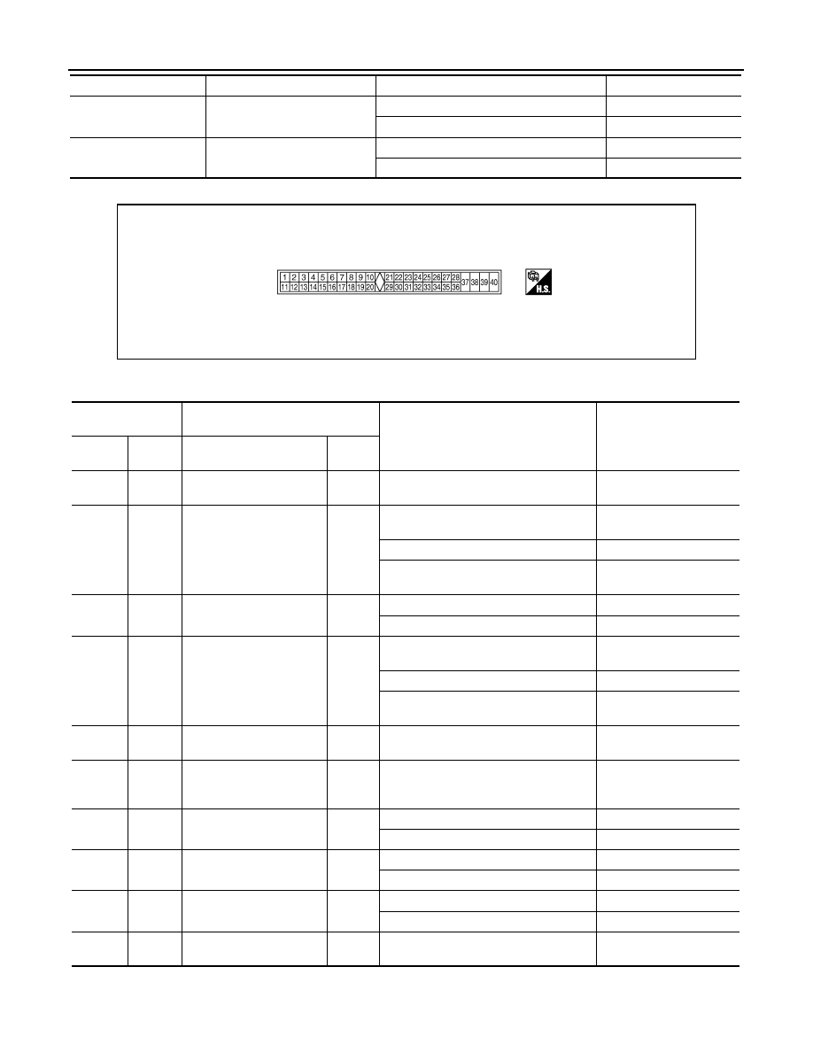
TERMINAL LAYOUT
PHYSICAL VALUES
FAIL SAFE
Fail-safe condition
Fail-safe condition
ON
Normal
OFF
WARNING LAMP
RAS warning lamp condition
RAS warning lamp: ON
ON
RAS warning lamp: OFF
OFF
Monitor item
Content
Condition
Value/Status
SGIA1449E
Terminal No.
(Wire color)
Description
Condition
Value (Approx.)
+
-
Signal name
Input/
Output
1
(L)
—
CAN-H
—
—
—
4
(Y)
Ground
Rear wheel steering angle
sensor (main) output volt-
age
Output
RAS actuator assembly turns right com-
pletely.
4.4 V
RAS actuator assembly is neutral
2.4 V
RAS actuator assembly turns left com-
pletely.
0.4 V
5
(W)
Ground
Rear wheel steering angle
sensor power supply
Output
Ignition switch: ON
5 V
Ignition switch: OFF
0 V
7
(R)
Ground
Rear wheel steering angle
sensor (sub) output voltage
Output
RAS actuator assembly turns right com-
pletely.
4.4 V
RAS actuator assembly is neutral
2.6 V
RAS actuator assembly turns left com-
pletely.
0.4 V
8
(P)
—
CAN-L
—
—
—
15
(G)
Ground
Ground
(Rear wheel steering angle
sensor)
—
Always
0 V
22
(GR)
Ground
Stop lamp switch
Input
Brake pedal: Depressed
Battery voltage
Brake pedal: Released
0 V
25
(SB)
Ground
RAS motor relay
Output
Ignition switch: ON
Battery voltage
Ignition switch: OFF
0 V
27
(G)
Ground
Ignition switch
Input
Ignition switch: ON
Battery voltage
Ignition switch: OFF
0 V
34
(GR)
Ground
Ground
—
Always
0 V

RAS CONTROL UNIT
STC-91
< ECU DIAGNOSIS INFORMATION >
[WITH REAR ACTIVE STEER]
C
D
E
F
H
I
J
K
L
M
A
B
STC
N
O
P
CAUTION:
When using circuit tester to measure voltage for inspection, never forcibly extend any connector terminals.
36
(LG)
Ground
Power steering solenoid
valve
Output
Vehicle speed: 0 km/h (0 MPH)
(Engine is running)
4.4 – 6.6 V
Vehicle speed: 100 km/h (62 MPH)
2.4 – 3.6 V
37
(P)
Ground
RAS motor power supply
Input
Ignition switch: ON
Battery voltage
Ignition switch: OFF
0 V
38
(G/Y)
Ground
RAS motor output voltage
(right)
Output
While RAS motor activates rightward
Battery voltage
While RAS motor activates leftward
0 V
39
(G/R)
Ground
RAS motor output voltage
(left)
Output
While RAS motor activates rightward
0 V
While RAS motor activates leftward
Battery voltage
40
(B)
Ground
Ground
(RAS motor)
—
Always
0 V
Terminal No.
(Wire color)
Description
Condition
Value (Approx.)
+
-
Signal name
Input/
Output
STC-92
< ECU DIAGNOSIS INFORMATION >
[WITH REAR ACTIVE STEER]
RAS CONTROL UNIT
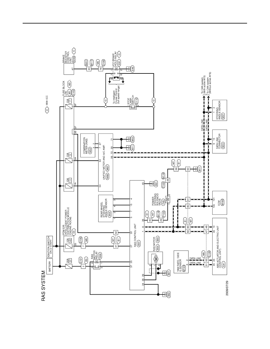
Wiring Diagram - RAS SYSTEM -
INFOID:0000000005612695
JCGWA0243GB
Нет комментариевНе стесняйтесь поделиться с нами вашим ценным мнением.
Текст