Infiniti FX35, FX50 (S51). Manual — part 1785
POWER SUPPLY AND GROUND CIRCUIT
STC-81
< DTC/CIRCUIT DIAGNOSIS >
[WITH REAR ACTIVE STEER]
C
D
E
F
H
I
J
K
L
M
A
B
STC
N
O
P
POWER SUPPLY AND GROUND CIRCUIT
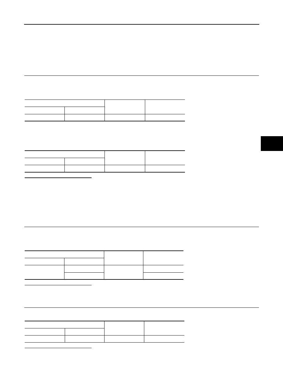
Description
INFOID:0000000005549735
Supplies power to RAS control unit.
Diagnosis Procedure
INFOID:0000000005549736
1.
CHECK RAS CONTROL UNIT POWER SUPPLY
1.
Turn the ignition switch OFF.
2.
Disconnect RAS control unit harness connector.
3.
Check the voltage between RAS control unit harness connectors and ground.
4.
Turn the ignition switch ON.
CAUTION:
Never start the engine.
5.
Check the voltage between RAS control unit harness connectors and the ground.
Is the inspection result normal?
YES
>> GO TO 2.
NO
>>
Check the following items. Repair or replace the malfunctioning parts.
• 10A fuse (#45) open
- Short among 10A fuse (#45) connector, RAS control unit harness connector No. 27 terminal and
the ground
• Open between the ignition switch and RAS control unit harness connector No. 27 terminal
• Ignition switch
2.
CHECK RAS MOTOR POWER SUPPLY CIRCUIT (1)
1.
Turn the ignition switch OFF.
2.
Remove RAS motor relay.
3.
Check the continuity between RAS motor relay harness connector and ground.
Is the inspection result normal?
YES
>> GO TO 3.
NO
>> Repair or replace the harnesses and connectors.
3.
CHECK RAS MOTOR POWER SUPPLY CIRCUIT (2)
Check the voltage between RAS motor relay harness connector and ground.
Is the inspection result normal?
RAS control unit
—
Voltage (Approx.)
Connector
Terminal
B37
27
Ground
0 V
RAS control unit
—
Voltage (Approx.)
Connector
Terminal
B37
27
Ground
Battery voltage
RAS motor relay
—
Continuity
Connector
Terminal
B36
2
Ground
Existed
1
Not existed
RAS motor relay
—
Voltage (Approx.)
Connector
Terminal
B36
3 Ground
Battery
voltage

STC-82
< DTC/CIRCUIT DIAGNOSIS >
[WITH REAR ACTIVE STEER]
POWER SUPPLY AND GROUND CIRCUIT
YES
>> GO TO 4.
NO
>>
Check the following items. Repair or replace the malfunctioning parts.
• 20A fuse (#37) open
- Short among 20A fuse (#37) connector, RAS motor relay harness connector No. 3 terminal and
the ground
• Open between the battery and RAS motor relay harness connector No. 3 terminal
4.
CHECK RAS MOTOR POWER SUPPLY CIRCUIT (3)
1.
Connect RAS control unit harness connector.
2.
Install RAS motor relay.
3.
Turn the ignition switch ON.
CAUTION:
Never start the engine.
4.
Check the voltage between RAS control unit harness connector and ground.
5.
Turn the ignition switch OFF.
Is the inspection result normal?
YES
>> GO TO 5.
NO
>> Replace RAS control unit. Refer to
STC-109, "Removal and Installation"
.
5.
CHECK RAS MOTOR RELAY
Check the RAS motor relay. Refer to
STC-54, "Component Inspection"
.
Is the inspection result normal?
YES
>> GO TO 6.
NO
>> Replace RAS motor relay.
6.
CHECK RAS MOTOR POWER SUPPLY
1.
Connect RAS control unit harness connector.
2.
Install RAS motor relay.
3.
Turn the ignition switch ON.
CAUTION:
Never start the engine.
4.
Check the voltage between RAS control unit harness connectors and ground.
Is the inspection result normal?
YES
>> INSPECTION END
NO
>> Replace RAS control unit. Refer to
STC-109, "Removal and Installation"
.
RAS control unit
—
Voltage (Approx.)
Connector
Terminal
B37
25
Ground
Battery voltage
RAS control unit
—
Voltage (Approx.)
Connector
Terminal
B37
37
Ground
Battery voltage

POWER STEERING SOLENOID VALVE
STC-83
< DTC/CIRCUIT DIAGNOSIS >
[WITH REAR ACTIVE STEER]
C
D
E
F
H
I
J
K
L
M
A
B
STC
N
O
P
POWER STEERING SOLENOID VALVE
Description
INFOID:0000000005549739
The power steering oil pressure in the gear housing assembly is controlled.
Diagnosis Procedure
INFOID:0000000005549740
1.
CHECK POWER STEERING SOLENOID VALVE SIGNAL
With CONSULT-III
1.
Start the engine.
2.
Select “DATA MONITOR” of “4WAS(MAIN)/RAS/HICAS”.
3.
Check “POWER STR SOL” item on “DATA MONITOR” of RAS control unit.
Without CONSULT-III
1.
Start the engine.
2.
Check the voltage between RAS control unit harness connector and ground.
3.
Check that there is no malfunction in RAS control unit harness connector or disconnection.
Is the inspection result normal?
YES
>> GO TO 2.
NO
>> Replace RAS control unit. Refer to
STC-109, "Removal and Installation"
2.
CHECK POWER STEERING SOLENOID VALVE CIRCUIT
1.
Turn the ignition switch OFF.
2.
Disconnect RAS control unit harness connector.
3.
Disconnect the power steering solenoid valve harness connector.
4.
Check the continuity between RAS control unit harness connector and power steering solenoid valve har-
ness connector.
5.
Check the continuity between power steering solenoid valve harness connector and ground.
Is the inspection result normal?
YES
>> GO TO 3.
NO
>> Repair or replace the harnesses and connectors.
3.
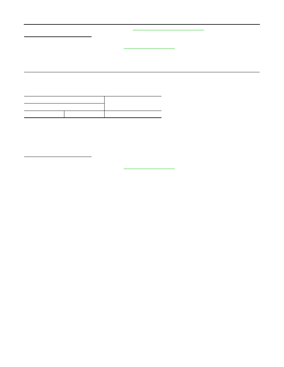
CHECK POWER STEERING SOLENOID VALVE
Monitor item
Condition
Display value
POWER STR SOL
Vehicle speed: 0 km/h (0 MPH)
(Engine is running)
Approx. 1.10 A
Vehicle speed: 100 km/h (62 MPH)
Approx. 0.42 A
RAS control unit
Data (Approx.)
Connector
Terminal
—
Condition
B37
36
Ground
Vehicle speed: 0 km/h (0 MPH)
(Engine is running)
4.4 – 6.6 V
Vehicle speed: 100 km/h (62 MPH)
2.4 – 3.6 V
RAS control unit
Power steering solenoid valve
Continuity
Connector
Terminal
Connector
Terminal
B37
36
F45
1
Existed
Power steering solenoid valve
—
Continuity
Connector
Terminal
F45
2
Ground
Existed
STC-84
< DTC/CIRCUIT DIAGNOSIS >
[WITH REAR ACTIVE STEER]
POWER STEERING SOLENOID VALVE
Check the power steering solenoid valve. Refer to
STC-84, "Component Inspection"
.
Is the inspection result normal?
YES
>> INSPECTION END
NO
>> Repair the steering gear. Refer to
Component Inspection
INFOID:0000000005549741
1.
POWER STEERING SOLENOID VALVE INSPECTION
1.
Turn the ignition switch OFF.
2.
Disconnect the power steering solenoid valve harness connector.
3.
Check the resistance between power steering solenoid valve connector terminals.
4.
Check for click sound (power steering solenoid valve activation sound) when applying approximately 12 V
between the power steering solenoid valve connector terminals.
CAUTION:
• Never make the terminals short.
• Assign the positive terminal to No. 1 terminal, and the negative terminal to No. 2 terminal. Con-
nect the fuse between the terminals when applying the voltage.
Is the inspection result normal?
YES
>> INSPECTION END
NO
>> Repair the steering gear. Refer to
Power steering solenoid valve
Resistance (Approx.)
Terminal
1
2
4 – 6
Ω
Нет комментариевНе стесняйтесь поделиться с нами вашим ценным мнением.
Текст