Infiniti FX35, FX50 (S51). Manual — part 764
ENGINE CONTROL SYSTEM
EC-597
< SYSTEM DESCRIPTION >
[VK50VE]
C
D
E
F
G
H
I
J
K
L
M
A
EC
N
P
O
Component Description
INFOID:0000000005237171
Component
Reference
A/F sensor 1
A/F sensor 1 heater
Accelerator pedal position sensor
ASCD brake switch
ASCD steering switch
Battery current sensor
Brake booster pressure sensor
Camshaft position sensor
Crankshaft position sensor
Cooling fan control module
Cooling fan motor
Electric throttle control actuator
Engine coolant temperature sensor
Engine oil temperature sensor
EVAP canister purge volume control solenoid valve
EVAP canister vent control valve
EVAP control system pressure sensor
Exhaust valve timing control solenoid valve
Exhaust valve timing control position sensor
Fuel injector
Fuel level sensor
Fuel pump
Fuel pump control module (FPCM)
Fuel tank temperature sensor
Heated oxygen sensor 2
Heated oxygen sensor 2 heater
ICC brake switch
ICC steering switch
Ignition coil with power transistor
Intake air temperature sensor
Intake valve timing control solenoid valve
Knock sensor
Mass air flow sensor
PCV valve
Power steering pressure sensor
Refrigerant pressure sensor
Snow mode switch
Stop lamp switch
Throttle control motor
Throttle control motor relay
Throttle position sensor
VVEL actuator motor

EC-598
< SYSTEM DESCRIPTION >
[VK50VE]
ENGINE CONTROL SYSTEM
VVEL actuator motor relay
VVEL control module
VVEL control shaft position sensor
Component
Reference
MULTIPORT FUEL INJECTION SYSTEM
EC-599
< SYSTEM DESCRIPTION >
[VK50VE]
C
D
E
F
G
H
I
J
K
L
M
A
EC
N
P
O
MULTIPORT FUEL INJECTION SYSTEM
System Diagram
INFOID:0000000005237172
System Description
INFOID:0000000005237173
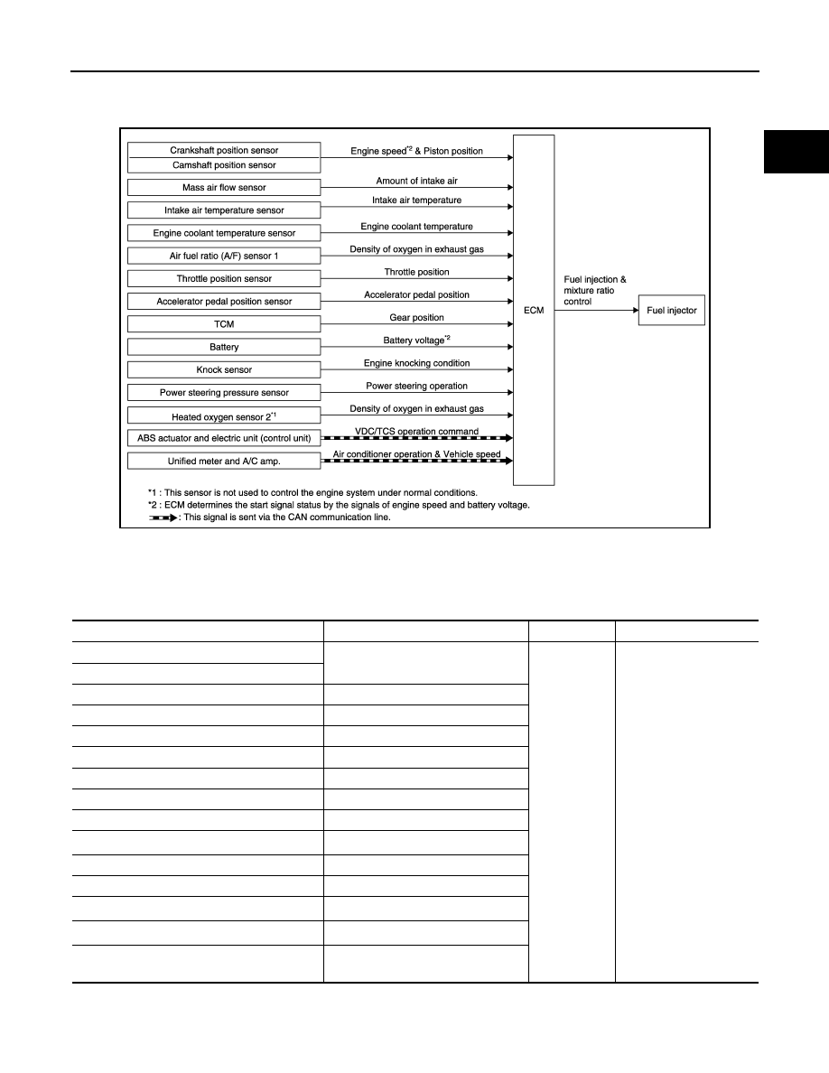
INPUT/OUTPUT SIGNAL CHART
*1: This sensor is not used to control the engine system under normal conditions.
*2: This signal is sent to the ECM via the CAN communication line.
*3: ECM determines the start signal status by the signals of engine speed and battery voltage.
JMBIA1534GB
Sensor
Input signal to ECM
ECM function
Actuator
Crankshaft position sensor
Engine speed*
3
Piston position
Fuel injection
& mixture ratio
control
Fuel injector
Camshaft position sensor
Mass air flow sensor
Amount of intake air
Intake air temperature sensor
Intake air temperature
Engine coolant temperature sensor
Engine coolant temperature
Air fuel ratio (A/F) sensor 1
Density of oxygen in exhaust gas
Throttle position sensor
Throttle position
Accelerator pedal position sensor
Accelerator pedal position
TCM
Gear position
Battery
Battery voltage*
3
Knock sensor
Engine knocking condition
Power steering pressure sensor
Power steering operation
Heated oxygen sensor 2*
1
Density of oxygen in exhaust gas
ABS actuator and electric unit (control unit)
VDC/TCS operation command*
2
Unified meter and A/C amp.
Vehicle speed & Air conditioner opera-
tion*
2
EC-600
< SYSTEM DESCRIPTION >
[VK50VE]
MULTIPORT FUEL INJECTION SYSTEM
SYSTEM DESCRIPTION
The amount of fuel injected from the fuel injector is determined by the ECM. The ECM controls the length of
time the valve remains open (injection pulse duration). The amount of fuel injected is a program value in the
ECM memory. The program value is preset by engine operating conditions. These conditions are determined
by input signals (for engine speed and intake air) from the crankshaft position sensor, camshaft position sen-
sor and the mass air flow sensor.
VARIOUS FUEL INJECTION INCREASE/DECREASE COMPENSATION
In addition, the amount of fuel injected is compensated to improve engine performance under various operat-
ing conditions as listed below.
<Fuel increase>
• During warm-up
• When starting the engine
• During acceleration
• Hot-engine operation
• When selector lever position is changed from N to D
• High-load, high-speed operation
<Fuel decrease>
• During deceleration
• During high engine speed operation
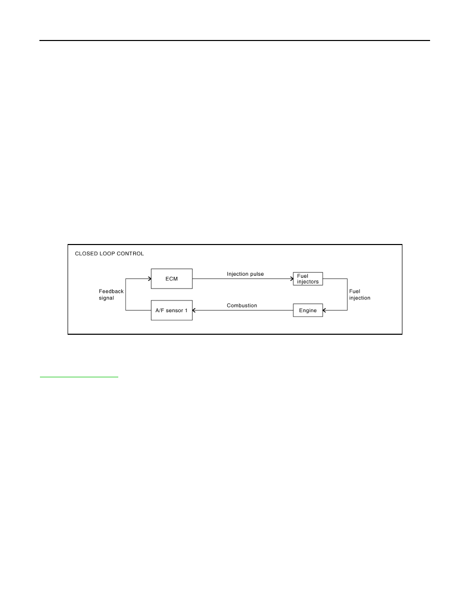
MIXTURE RATIO FEEDBACK CONTROL (CLOSED LOOP CONTROL)
The mixture ratio feedback system provides the best air-fuel mixture ratio for driveability and emission control.
The three way catalyst (manifold) can better reduce CO, HC and NOx emissions. This system uses A/F sen-
sor 1 in the exhaust manifold to monitor whether the engine operation is rich or lean. The ECM adjusts the
injection pulse width according to the sensor voltage signal. For more information about A/F sensor 1, refer to
. This maintains the mixture ratio within the range of stoichiometric (ideal air-fuel mix-
ture).
This stage is referred to as the closed loop control condition.
Heated oxygen sensor 2 is located downstream of the three way catalyst (manifold). Even if the switching
characteristics of A/F sensor 1 shift, the air-fuel ratio is controlled to stoichiometric by the signal from heated
oxygen sensor 2.
• Open Loop Control
The open loop system condition refers to when the ECM detects any of the following conditions. Feedback
control stops in order to maintain stabilized fuel combustion.
- Deceleration and acceleration
- High-load, high-speed operation
- Malfunction of A/F sensor 1 or its circuit
- Insufficient activation of A/F sensor 1 at low engine coolant temperature
- High engine coolant temperature
- During warm-up
- After shifting from N to D
- When starting the engine
MIXTURE RATIO SELF-LEARNING CONTROL
The mixture ratio feedback control system monitors the mixture ratio signal transmitted from A/F sensor 1.
This feedback signal is then sent to the ECM. The ECM controls the basic mixture ratio as close to the theoret-
ical mixture ratio as possible. However, the basic mixture ratio is not necessarily controlled as originally
designed. Both manufacturing differences (i.e., mass air flow sensor hot wire) and characteristic changes dur-
ing operation (i.e., fuel injector clogging) directly affect mixture ratio.
PBIB2793E
Нет комментариевНе стесняйтесь поделиться с нами вашим ценным мнением.
Текст