Infiniti FX35, FX50 (S51). Manual — part 765
MULTIPORT FUEL INJECTION SYSTEM
EC-601
< SYSTEM DESCRIPTION >
[VK50VE]
C
D
E
F
G
H
I
J
K
L
M
A
EC
N
P
O
Accordingly, the difference between the basic and theoretical mixture ratios is monitored in this system. This is
then computed in terms of “injection pulse duration” to automatically compensate for the difference between
the two ratios.
“Fuel trim” refers to the feedback compensation value compared against the basic injection duration. Fuel trim
includes “short-term fuel trim” and “long-term fuel trim”.
“Short term fuel trim” is the short-term fuel compensation used to maintain the mixture ratio at its theoretical
value. The signal from A/F sensor 1 indicates whether the mixture ratio is RICH or LEAN compared to the the-
oretical value. The signal then triggers a reduction in fuel volume if the mixture ratio is rich, and an increase in
fuel volume if it is lean.
“Long-term fuel trim” is overall fuel compensation carried out over time to compensate for continual deviation
of the “short-term fuel trim” from the central value. Continual deviation will occur due to individual engine differ-
ences, wear over time and changes in the usage environment.
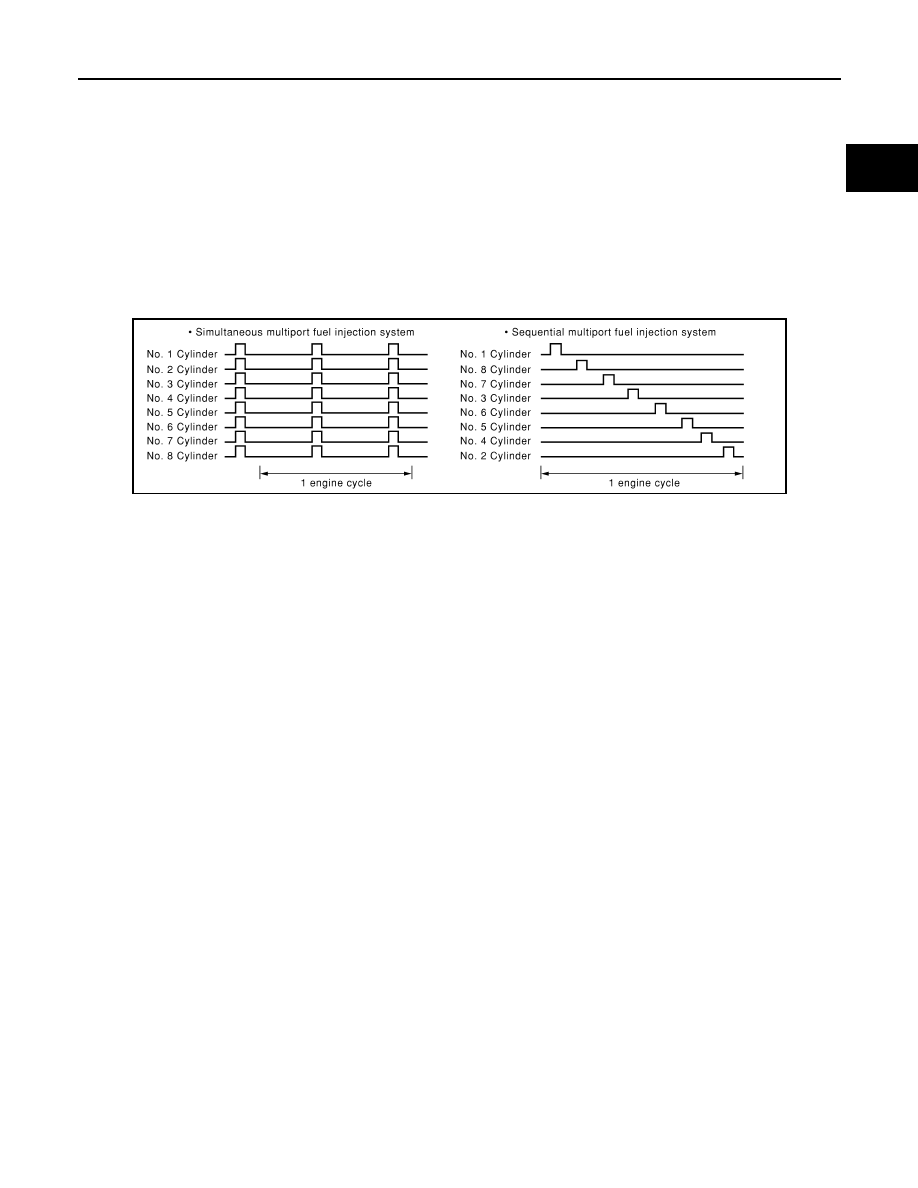
FUEL INJECTION TIMING
Two types of systems are used.
• Sequential Multiport Fuel Injection System
Fuel is injected into each cylinder during each engine cycle according to the ignition order. This system is
used when the engine is running.
• Simultaneous Multiport Fuel Injection System
Fuel is injected simultaneously into all eight cylinders twice each engine cycle. In other words, pulse signals
of the same width are simultaneously transmitted from the ECM.
The eight fuel injectors will then receive the signals 2 times for each engine cycle.
This system is used when the engine is being started and/or if the fail-safe system (CPU) is operating.
FUEL SHUT-OFF
Fuel to each cylinder is cut off during deceleration, operation of the engine at excessively high speed or oper-
ation of the vehicle at excessively high speed.
PBIB0122E
EC-602
< SYSTEM DESCRIPTION >
[VK50VE]
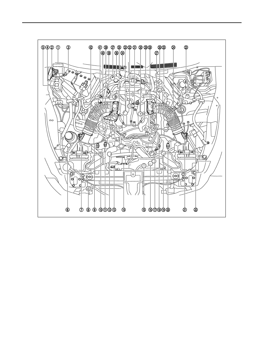
MULTIPORT FUEL INJECTION SYSTEM
Component Parts Location
INFOID:0000000005589019
1.
IPDM E/R
2.
VVEL control module
3.
Battery current sensor
4.
VVEL actuator motor relay
5.
Cooling fan relay-1
6.
Cooling fan relay-2
7.
Mass air flow sensor (bank 2)
8.
Refrigerant pressure sensor
9.
Exhaust valve timing control position
sensor (bank 2)
10. Exhaust valve timing control sole-
noid valve (bank 2)
11.
Camshaft position sensor (bank 2)
12. Intake valve timing control solenoid
valve (bank 2)
13. Cooling fan motor-1
14. Cooling fan control module-1
15. Cooling fan motor-2
16. Cooling fan control module-2
17. Intake valve timing control solenoid
valve (bank 1)
18. Camshaft position sensor (bank 1)
19. Exhaust valve timing control sole-
noid valve (bank 1)
20. Exhaust valve timing control position
sensor (bank 1)
21. Mass air flow sensor (with intake air
temperature sensor) (bank 1)
22. ICC brake hold relay (ICC models)
23. Brake booster pressure sensor
24. Ignition coil (with power transistor)
and spark plug (bank 1)
25. VVEL actuator motor (bank 1)
26. VVEL control shaft position sensor
(bank 1)
27. Fuel injector (bank 1)
28. Electric throttle control actuator
(bank 1)
29. A/F sensor 1 (bank 1)
30. Knock sensor (bank 1)
JMBIA1535ZZ
MULTIPORT FUEL INJECTION SYSTEM
EC-603
< SYSTEM DESCRIPTION >
[VK50VE]
C
D
E
F
G
H
I
J
K
L
M
A
EC
N
P
O
31. EVAP canister purge volume con-
trol solenoid valve
32. Manifold Absolute Pressure Sensor
(This sensor is not for controlling the
engine system, nor for the on board
diagnosis.)
33. Knock sensor (bank 2)
34. Crankshaft position sensor
35. Electric throttle control actuator
(bank2)
36. VVEL actuator motor (bank 2)
37. VVEL control shaft position sensor
(bank 2)
38. A/F sensor 1 (bank 2)
39. Engine coolant temperature sensor
40. Fuel injector (bank 2)
41. EVAP service port
42. Ignition coil (with power transistor)
and spark plug (bank 2)
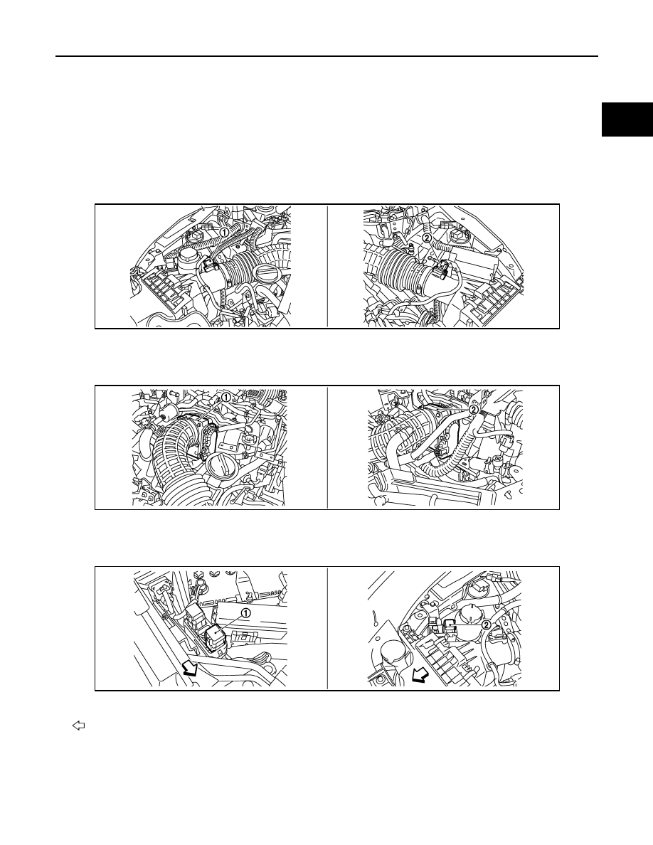
1.
Mass air flow sensor (bank 2)
2.
Mass air flow sensor (with intake air
temperature sensor) (bank 1)
1.
Electric throttle control actuator
(bank 2)
2.
Electric throttle control actuator
(bank 1)
1.
Cooling fan relay-1
2.
Cooling fan relay-2
Vehicle front
JMBIA1536ZZ
JMBIA1537ZZ
JMBIA1538ZZ
EC-604
< SYSTEM DESCRIPTION >
[VK50VE]
MULTIPORT FUEL INJECTION SYSTEM
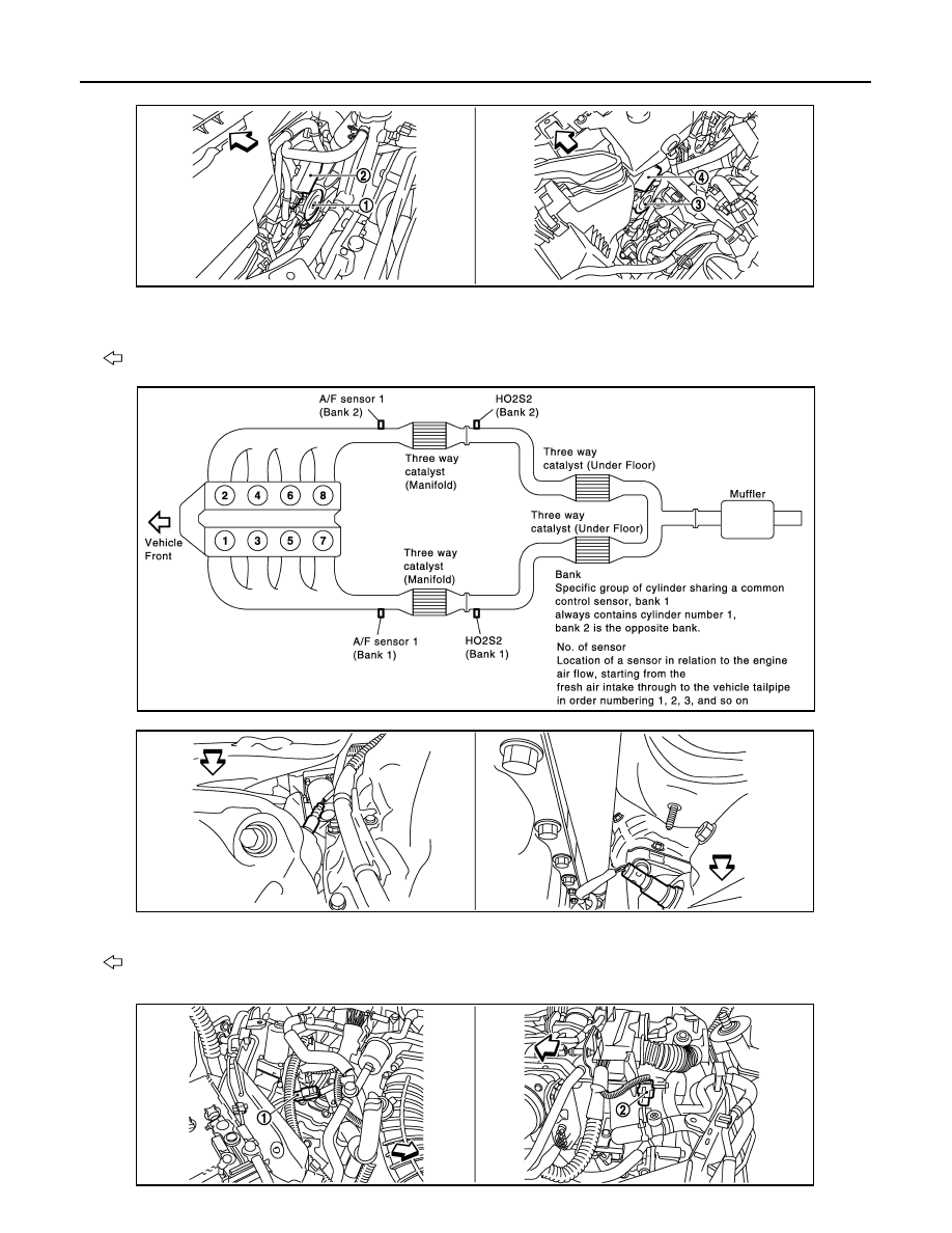
1.
Cooling fan motor-1
2.
Cooling fan control module-1
3.
Cooling fan motor-2
4.
Cooling fan control module-2
Vehicle front
JMBIA1539ZZ
JMBIA1576GB
1.
A/F sensor 1 (bank 1)
2.
A/F sensor 1 (bank 2)
Vehicle front
JMBIA1540ZZ
JMBIA1541ZZ
Нет комментариевНе стесняйтесь поделиться с нами вашим ценным мнением.
Текст