Infiniti FX35, FX50 (S51). Manual — part 887

P2A00, P2A03 A/F SENSOR 1
EC-1089
< DTC/CIRCUIT DIAGNOSIS >
[VK50VE]
C
D
E
F
G
H
I
J
K
L
M
A
EC
N
P
O
3.
Turn ignition switch ON.
4.
Turn ignition switch OFF and wait at least 10 seconds.
5.
Start engine and keep the engine speed between 3,500 and 4,000 rpm for 1 minute under no load.
6.
Let engine idle for 1 minute.
7.
Keep engine speed between 2,500 and 3,000 rpm for 20 minutes.
8.
Check 1st trip DTC.
Is 1st trip DTC detected?
YES
>> Go to
EC-1089, "Diagnosis Procedure"
NO
>> INSPECTION END
Diagnosis Procedure
INFOID:0000000005237591
1.
CHECK GROUND CONNECTION
1.
Turn ignition switch OFF.
2.
Check ground connection M95. Refer to Ground Inspection in
Is the inspection result normal?
YES
>> GO TO 2.
NO
>> Repair or replace ground connection.
2.
RETIGHTEN A/F SENSOR 1
Loosen and retighten the A/F sensor 1. Refer to
EM-205, "Disassembly and Assembly"
.
>> GO TO 3.
3.
CHECK A/F SENSOR 1 CONNECTOR
1.
Disconnect A/F sensor 1 harness connector.
2.
Check that water is not inside connectors.
Is the inspection result normal?
YES
>> GO TO 4.
NO
>> Repair or replace harness connector.
4.
CHECK FOR INTAKE AIR LEAKAGE
1.
Reconnect A/F sensor 1 harness connector.
2.
Start engine and run it at idle.
3.
Listen for an intake air leakage after the mass air flow sensor.
Is intake air leakage detected?
YES
>> Repair or replace malfunctioning part.
NO
>> GO TO 5.
5.
CLEAR THE MIXTURE RATIO SELF-LEARNING VALUE
1.
Clear the mixture ratio self-learning value. Refer to
EC-585, "MIXTURE RATIO SELF-LEARNING VALUE
CLEAR : Special Repair Requirement"
.
2.
Run engine for at least 10 minutes at idle speed.
Is the 1st trip DTC P0171, P0172, P0174 or P0175 detected? Is it difficult to start engine?
YES
>> Perform trouble diagnosis for DTC P0171, P0174 or P0172, P0175. Refer to
or
NO
>> GO TO 6.
6.
CHECK A/F SENSOR 1 POWER SUPPLY CIRCUIT
1.
Turn ignition switch OFF and then turn it ON.
2.
Disconnect A/F sensor 1 harness connector.
3.
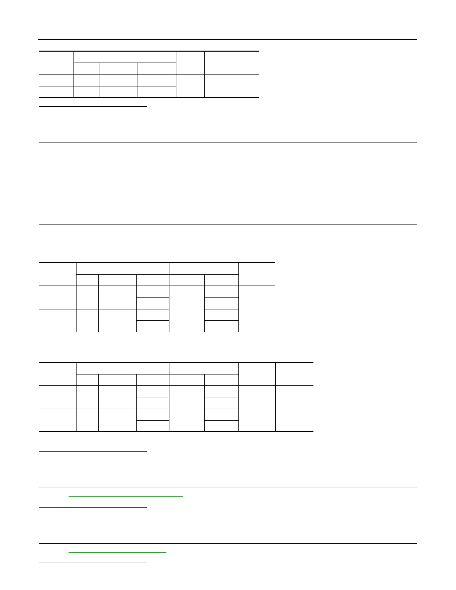
Check the voltage between A/F sensor 1 harness connector and ground.
EC-1090
< DTC/CIRCUIT DIAGNOSIS >
[VK50VE]
P2A00, P2A03 A/F SENSOR 1
Is the inspection result normal?
YES
>> GO TO 8.
NO
>> GO TO 7.
7.
DETECT MALFUNCTIONING PART
Check the following.
• Harness connectors E10, F10
• IPDM E/R harness connector E7
• 15 A fuse (No. 46)
• Harness for open or short between A/F sensor 1 and fuse
>> Repair or replace harness or connectors.
8.
CHECK A/F SENSOR 1 INPUT SIGNAL CIRCUIT FOR OPEN AND SHORT
1.
Turn ignition switch OFF.
2.
Disconnect ECM harness connector.
3.
Check the continuity between A/F sensor 1 harness connector and ECM harness connector.
4.
Check the continuity between A/F sensor 1 harness connector and ground or ECM harness connector
and ground.
5.
Also check harness for short to power.
Is the inspection result normal?
YES
>> GO TO 9.
NO
>> Repair open circuit, short to ground or short to power in harness or connectors.
9.
CHECK A/F SENSOR 1 HEATER
EC-762, "Component Inspection"
Is the inspection result normal?
YES
>> GO TO 10.
NO
>> GO TO 11.
10.
CHECK INTERMITTENT INCIDENT
Perform
GI-36, "Intermittent Incident"
.
Is the inspection result normal?
DTC
A/F sensor 1
Ground
Voltage
Bank
Connector
Terminal
P2A00
1
F67
4
Ground
Battery voltage
P2A03
2
F68
4
DTC
A/F sensor 1
ECM
Continuity
Bank
Connector
Terminal
Connector
Terminal
P2A00
1
F67
1
F111
81
Existed
2
82
P2A03
2
F68
1
85
2
86
DTC
A/F sensor 1
ECM
Ground
Continuity
Bank
Connector
Terminal
Connector
Terminal
P2A00
1
F67
1
F111
81
Ground
Not existed
2
82
P2A03
2
F68
1
85
2
86

P2A00, P2A03 A/F SENSOR 1
EC-1091
< DTC/CIRCUIT DIAGNOSIS >
[VK50VE]
C
D
E
F
G
H
I
J
K
L
M
A
EC
N
P
O
YES
>> GO TO 11.
NO
>> Repair or replace malfunctioning part.
11.
REPLACE AIR FUEL RATIO (A/F) SENSOR 1
Replace air fuel ratio (A/F) sensor 1.
CAUTION:
• Discard any A/F sensor which has been dropped from a height of more than 0.5 m (19.7 in) onto a
hard surface such as a concrete floor; use a new one.
• Before installing new A/F sensor, clean exhaust system threads using Oxygen Sensor Thread
Cleaner [commercial service tool (J-43897-18 or J-43897-12)] and approved anti-seize lubricant
(commercial service tool).
Will CONSULT-III be used?
YES
>> GO TO 12.
NO
>> GO TO 13.
12.
CONFIRM A/F ADJUSTMENT DATA
With CONSULT-III
1.
Turn ignition switch ON.
2.
Select “A/F ADJ-B1” and “A/F ADJ-B2” in “DATA MONITOR” mode with CONSULT-III.
3.
Check that “0.000” is displayed on CONSULT-III screen.
Is “0.000” displayed?
YES
>> INSPECTION END
NO
>> GO TO 13.
13.
CLEAR THE MIXTURE RATIO SELF-LEARNING VALUE
Clear the mixture ratio self-learning value. Refer to
EC-585, "MIXTURE RATIO SELF-LEARNING VALUE
CLEAR : Special Repair Requirement"
Will CONSULT-III be used?
YES
>> GO TO 14.
NO
>> INSPECTION END
14.
CONFIRM A/F ADJUSTMENT DATA
With CONSULT-III
1.
Turn ignition switch ON.
2.
Select “A/F ADJ-B1” and “A/F ADJ-B2” in “DATA MONITOR” mode with CONSULT-III.
3.
Check that “0.000” is displayed on CONSULT-III screen.
>> INSPECTION END
EC-1092
< DTC/CIRCUIT DIAGNOSIS >
[VK50VE]
ASCD BRAKE SWITCH
ASCD BRAKE SWITCH
Description
INFOID:0000000005237592
When the brake pedal is depressed, ASCD brake switch is turned OFF and stop lamp switch is turned ON.
ECM detects the state of the brake pedal by two kinds of input (ON/OFF signal).
Refer to
Component Function Check
INFOID:0000000005237593
1.
CHECK ASCD BRAKE SWITCH FUNCTION
With CONSULT-III
1.
Turn ignition switch ON.
2.
Select “BRAKE SW1” in “DATA MONITOR” mode with CONSULT-III.
3.
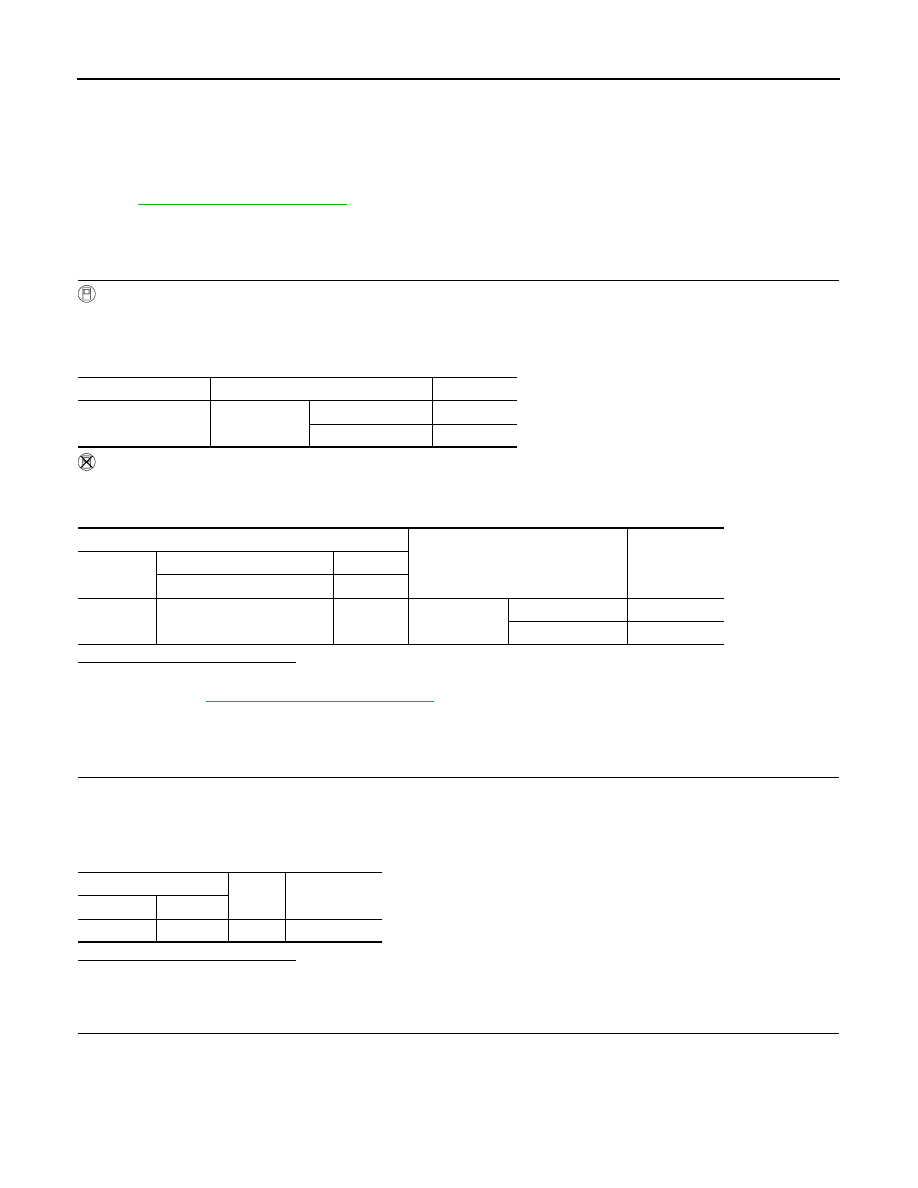
Check “BRAKE SW1” indication under the following conditions.
Without CONSULT-III
1.
Turn ignition switch ON.
2.
Check the voltage between ECM harness connector terminals as per the following.
Is the inspection result normal?
YES
>> INSPECTION END
NO
>> Go to
EC-1092, "Diagnosis Procedure"
Diagnosis Procedure
INFOID:0000000005237594
1.
CHECK ASCD BRAKE SWITCH POWER SUPPLY CIRCUIT
1.
Turn ignition switch OFF.
2.
Disconnect ASCD brake switch harness connector.
3.
Turn ignition switch ON.
4.
Check the voltage between ASCD brake switch harness connector and ground.
Is the inspection result normal?
YES
>> GO TO 3.
NO
>> GO TO 2.
2.
DETECT MALFUNCTIONING PART
Check the following.
• Fuse block (J/B) connector E103
• 10 A fuse (No. 3)
• Harness for open or short between ASCD brake switch and fuse
Monitor item
Condition
Indication
BRAKE SW1
(ASCD brake switch)
Brake pedal
Slightly depressed
OFF
Fully released
ON
ECM
Condition
Voltage (V)
Connector
+
–
Terminal
Terminal
M160
117
(ASCD brake switch signal)
128
Brake pedal
Slightly depressed
Approx. 0
Fully released
Battery voltage
ASCD brake switch
Ground
Voltage
Connector
Terminal
E109
1
Ground
Battery voltage
Нет комментариевНе стесняйтесь поделиться с нами вашим ценным мнением.
Текст