Infiniti FX35, FX50 (S51). Manual — part 1831
SELECTOR LEVER POSITION INDICATOR
TM-131
< DTC/CIRCUIT DIAGNOSIS >
[7AT: RE7R01A (VQ35HR)]
C
E
F
G
H
I
J
K
L
M
A
B
TM
N
O
P
Is the inspection result normal?
YES
>> Check intermittent incident. Refer to
GI-36, "Intermittent Incident"
.
NO
>> Replace damaged parts.
8.
CHECK HARNESS BETWEEN A/T SHIFT SELECTOR AND BCM (PART 1)
1.
Turn ignition switch OFF.
2.
Disconnect BCM connector.
3.
Check continuity between A/T shift selector vehicle side harness connector terminal and BCM vehicle
side harness connector terminal.
Is the inspection result normal?
YES
>> GO TO 9.
NO
>> Repair or replace damaged parts.
9.
CHECK HARNESS BETWEEN A/T SHIFT SELECTOR AND BCM (PART 2)
Check continuity between A/T shift selector vehicle side harness connector terminal and ground.
Is the inspection result normal?
YES
>> GO TO 10.
NO
>> Repair or replace damaged parts.
10.
CHECK BCM INPUT/OUTPUT SIGNAL
Check BCM input/output signal. Refer to
.
Is the inspection result normal?
YES
>> Check intermittent incident. Refer to
GI-36, "Intermittent Incident"
.
NO
>> Repair or replace damaged parts.
11.
CHECK POWER SOURCE
1.
Turn ignition switch OFF.
2.
Disconnect A/T shift selector connector.
3.
Turn ignition switch ON.
4.
Check voltage between A/T shift selector vehicle side harness connector terminals.
Is the inspection result normal?
YES
>> GO TO 12.
NO
>> Check illumination circuit. Refer to
INL-89, "Wiring Diagram - ILLUMINATION -"
.
12.
CHECK SHIFT POSITION SWITCH
1.
Disconnect shift position switch connector.
2.
Check continuity between A/T shift selector harness connector terminals and shift position switch connec-
tor terminals.
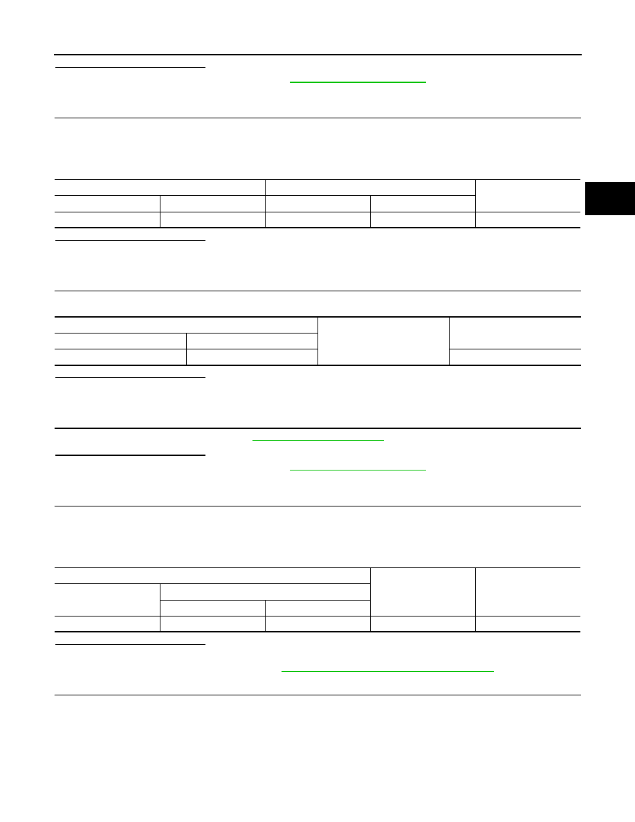
A/T shift selector vehicle side harness connector
BCM vehicle side harness connector
Continuity
Connector
Terminal
Connector
Terminal
M137
10
M122
96
Existed
A/T shift selector vehicle side harness connector
Ground
Continuity
Connector
Terminal
M137
10
Not existed
A/T shift selector vehicle side harness connector
Condition
Voltage (Approx.)
Connector
Terminal
+
−
M137
7
9
Lighting switch 1ST
Battery voltage

TM-132
< DTC/CIRCUIT DIAGNOSIS >
[7AT: RE7R01A (VQ35HR)]
SELECTOR LEVER POSITION INDICATOR
Is the inspection result normal?
YES
>> GO TO 13.
NO
>> Repair or replace damaged parts. Refer to
13.
CHECK HARNESS BETWEEN SHIFT POSITION SWITCH AND SELECTOR LEVER POSITION INDI-
CATOR (PART 3)
1.
Disconnect selector lever position indicator connector.
2.
Check continuity between shift position switch harness connector terminals and selector lever position
indicator connector terminals.
Is the inspection result normal?
YES
>> GO TO 6.
NO
>> Repair or replace damaged parts. Refer to
Component Inspection (Selector Lever Position Indicator)
INFOID:0000000005250133
1.
CHECK SELECTOR LEVER POSITION INDICATOR
Check that selector lever position indicator lamps turn on.
CAUTION:
Connect the fuse between the terminals when applying the voltage.
Is the inspection result normal?
YES
>> INSPECTION END
NO
>> Replace the selector lever position indicator. Refer to
A/T shift selector harness connector
Shift position switch connector
Continuity
Connector
Terminal
Connector
Terminal
M137
7
M221
10
Existed
2, 3, 4, 5, 6, 7, 9, 11
No existed
9
11
Existed
2, 3, 4, 5, 6, 7, 9, 10
No existed
Shift position switch harness connector
Selector lever position indicator harness connector
Continuity
Connector
Terminal
Connector
Terminal
M221
10
M223
1
Existed
11
9
Selector lever position indicator connector
Condition
Status
Connector
Terminal
+ (fuse)
−
M223
1
9
Apply 12 V direct current be-
tween terminals 1 and 9.
Illumination lamp turns on.
3
8
Apply 12 V direct current be-
tween terminals 3 and 8.
“N” position indicator lamp
turns on.
4
Apply 12 V direct current be-
tween terminals 4 and 8.
“D” position indicator lamp
turns on.
5
Apply 12 V direct current be-
tween terminals 5 and 8.
“R” position indicator lamp
turns on.
7
Apply 12 V direct current be-
tween terminals 7 and 8.
“P” position indicator lamp
turns on.
6
2
Apply 12 V direct current be-
tween terminals 6 and 2.
“M” mode indicator lamp
turns on.

TCM
TM-133
< ECU DIAGNOSIS INFORMATION >
[7AT: RE7R01A (VQ35HR)]
C
E
F
G
H
I
J
K
L
M
A
B
TM
N
O
P
ECU DIAGNOSIS INFORMATION
TCM
Reference Value
INFOID:0000000005250134
VALUES ON DIAGNOSIS TOOL
NOTE:
1.
The CONSULT-III electrically displays shift timing and lock-up timing (that is, operation timing of each
solenoid).
Check for time difference between actual shift timing and the CONSULT-III display. If the difference is
noticeable, mechanical parts (except solenoids, sensors, etc.) may be malfunctioning. Check mechanical
parts using applicable diagnostic procedures.
2.
Shift schedule (which implies gear position) displayed on CONSULT-III and that indicated in Service Man-
ual may differ slightly. This occurs because of the following reasons:
-
Actual shift schedule has more or less tolerance or allowance
-
Shift schedule indicated in Service Manual refers to the point where shifts start
-
Gear position displayed on CONSULT-III indicates the point where shifts are completed
3.
Display of solenoid valves on CONSULT-III changes at the start of shifting, while gear position is displayed
upon completion of shifting (which is computed by TCM).
CONSULT-III MONITOR ITEM
Item name
Condition
Value / Status (Approx.)
VHCL/S SE-A/T
During driving
Approximately matches the speed-
ometer reading.
ESTM VSP SIG
During driving
Approximately matches the speed-
ometer reading.
OUTPUT REV
During driving (lock-up ON)
Tachometer/Gear ratio
INPUT SPEED
During driving (lock-up ON)
Approximately matches the engine
speed.
F SUN GR REV
During driving
Revolution of front sun gear is indi-
cated.
F CARR GR REV
During driving
Revolution of front carrier is indi-
cated.
ENGINE SPEED
Engine running
Closely matches the tachometer
reading.
TC SLIP SPEED
During driving
Engine speed
−
Input speed
ACCELE POSI
Released accelerator pedal
0.0/8
Fully depressed accelerator pedal
8.0/8
THROTTLE POSI
Released accelerator pedal
0.0/8
Fully depressed accelerator pedal
8.0/8
ATF TEMP 1
Ignition switch ON
Temperature of ATF in the oil pan is
indicated.
ATF TEMP 2
Ignition switch ON
Temperature of ATF at the exit of
torque converter.
ATF TEMP SE 1
0
°
C (32
°
F) – 20
°
C (68
°
F) – 80
°
C (176
°
F)
3.3 – 2.7 – 0.9 V
BATTERY VOLT
Ignition switch ON
Battery voltage (11 V – 14 V)
LINE PRES SOL
During driving
0.2 – 0.6 A
TCC SOLENOID
Slip lock-up is active
0.2 – 0.8 A
Lock-up is active
0.8 A
Other than the above
0 A
L/B SOLENOID
Low brake engaged
0.6 – 0.8 A
Low brake disengaged
0 – 0.05 A

TM-134
< ECU DIAGNOSIS INFORMATION >
[7AT: RE7R01A (VQ35HR)]
TCM
FR/B SOLENOID
Front brake engaged
0.6 – 0.8 A
Front brake disengaged
0 – 0.05 A
HLR/C SOL
High and low reverse clutch disengaged
0.6 – 0.8 A
High and low reverse clutch engaged
0 – 0.05 A
I/C SOLENOID
Input clutch disengaged
0.6 – 0.8 A
Input clutch engaged
0 – 0.05 A
D/C SOLENOID
Direct clutch disengaged
0.6 – 0.8 A
Direct clutch engaged
0 – 0.05 A
2346/B SOL
2346 brake engaged
0.6 – 0.8 A
2346 brake disengaged
0 – 0.05 A
L/P SOL MON
During driving
0.2 – 0.6 A
TCC SOL MON
Slip lock-up is active
0.2 – 0.8 A
Lock-up is active
0.8 A
Other than the above
0 A
L/B SOL MON
Low brake engaged
0.6 – 0.8 A
Low brake disengaged
0 – 0.05 A
FR/B SOL MON
Front brake engaged
0.6 – 0.8 A
Front brake disengaged
0 – 0.05 A
HLR/C SOL MON
High and low reverse clutch disengaged
0.6 – 0.8 A
High and low reverse clutch engaged
0 – 0.05 A
I/C SOL MON
Input clutch disengaged
0.6 – 0.8 A
Input clutch engaged
0 – 0.05 A
D/C SOL MON
Direct clutch disengaged
0.6 – 0.8 A
Direct clutch engaged
0 – 0.05 A
2346/B SOL MON
2346 brake engaged
0.6 – 0.8 A
2346 brake disengaged
0 – 0.05 A
GEAR RATIO
Driving with 1GR
4.924
Driving with 2GR
3.194
Driving with 3GR
2.043
Driving with 4GR
1.412
Driving with 5GR
1.000
Driving with 6GR
0.862
Driving with 7GR
0.772
ENGINE TORQUE
During driving
Changes the value according to
the acceleration or deceleration.
ENG TORQUE D
During driving
Changes the value according to
the acceleration or deceleration.
INPUT TRQ S
During driving
Changes the value according to
the acceleration or deceleration.
INPUT TRQ L/P
During driving
Changes the value according to
the acceleration or deceleration.
TRGT PRES L/P
Selector lever in “P” and “N” positions
490 kPa
Other than the above
490 – 1370 kPa
TRGT PRES TCC
Slip lock-up is active
0 – 600 kPa
Lock-up is active
600 kPa
Other than the above
0 kPa
Item name
Condition
Value / Status (Approx.)
Нет комментариевНе стесняйтесь поделиться с нами вашим ценным мнением.
Текст