Infiniti FX35, FX50 (S51). Manual — part 1832

TCM
TM-135
< ECU DIAGNOSIS INFORMATION >
[7AT: RE7R01A (VQ35HR)]
C
E
F
G
H
I
J
K
L
M
A
B
TM
N
O
P
TRGT PRES L/B
Low brake engaged
1370 kPa
Low brake disengaged
0 kPa
TRGT PRES FR/B
Front brake engaged
1370 kPa
Front brake disengaged
0 kPa
TRG PRE HLR/C
High and low reverse clutch disengaged
1370 kPa
High and low reverse clutch engaged
0 kPa
TRGT PRES I/C
Input clutch disengaged
1370 kPa
Input clutch engaged
0 kPa
TRGT PRES D/C
Direct clutch disengaged
1370 kPa
Direct clutch engaged
0 kPa
TRG PRE 2346/B
2346 brake engaged
1370 kPa
2346 brake disengaged
0 kPa
SHIFT PATTERN
During normal driving (without shift changes)
FF
VEHICLE SPEED
During driving
Approximately matches the speed-
ometer reading.
RANGE SW 4
Selector lever in “P” and “N” positions
ON
Other than the above
OFF
RANGE SW 3
Selector lever in “P”, “R” and “N” positions
ON
Other than the above
OFF
RANGE SW 2
Selector lever in “P” and “R” positions
ON
Other than the above
OFF
RANGE SW 1
Selector lever in “P” position
ON
Other than the above
OFF
SFT DWN ST SW*
Paddle shifter (shift-down) is pulled
ON
Other than the above
OFF
SFT UP ST SW*
Paddle shifter (shift-up) is pulled
ON
Other than the above
OFF
DOWN SW LEVER
Selector lever is shifted to
−
side
ON
Other than the above
OFF
UP SW LEVER
Selector lever is shifted to + side
ON
Other than the above
OFF
NON M-MODE SW
Selector lever is shifted to manual shift gate side
OFF
Other than the above
ON
MANU MODE SW
Selector lever is shifted to manual shift gate side
ON
Other than the above
OFF
DS RANGE
Driving with DS mode
ON
Other than the above
OFF
1 POSITION SW*
Selector lever in “1” position
ON
Other than the above
OFF
OD CONT SW*
When overdrive control switch is depressed
ON
When overdrive control switch is released
OFF
BRAKESW
Depressed brake pedal
ON
Released brake pedal
OFF
POWERSHIFT SW*
Power mode
ON
Other than the above
OFF
Item name
Condition
Value / Status (Approx.)

TM-136
< ECU DIAGNOSIS INFORMATION >
[7AT: RE7R01A (VQ35HR)]
TCM
ASCD-OD CUT
When TCM receives ASCD OD cancel request signal
ON
Other than the above
OFF
ASCD-CRUISE
ASCD operate
ON
Other than the above
OFF
ABS SIGNAL
ABS operate
ON
Other than the above
OFF
TCS GR/P KEEP
When TCM receives TCS gear keep request signal
ON
Other than the above
OFF
TCS SIGNAL 2
When the reception value of A/T shift schedule change
demand signal is “cold”
ON
Other than the above
OFF
TCS SIGNAL 1
When the reception value of A/T shift schedule change
demand signal is “warm”
ON
Other than the above
OFF
LOW/B PARTS
At 4GR - 5GR - 6GR shift control
FAIL
Other than the above
NOTFAIL
HC/IC/FRB PARTS
At 1GR - 2GR - 3GR shift control
FAIL
Other than the above
NOTFAIL
IC/FRB PARTS
At 4GR - 5GR - 6GR shift control
FAIL
Other than the above
NOTFAIL
HLR/C PARTS
At 4GR - 5GR - 6GR shift control
FAIL
Other than the above
NOTFAIL
W/O THL POS
Fully depressed accelerator pedal
ON
Released accelerator pedal
OFF
CLSD THL POS
Released accelerator pedal
ON
Fully depressed accelerator pedal
OFF
DRV CST JUDGE
Depressed accelerator pedal
DRIVE
Released accelerator pedal
COAST
Item name
Condition
Value / Status (Approx.)

TCM
TM-137
< ECU DIAGNOSIS INFORMATION >
[7AT: RE7R01A (VQ35HR)]
C
E
F
G
H
I
J
K
L
M
A
B
TM
N
O
P
SHIFT IND SIGNAL
When the selector lever is positioned in between each po-
sition
OFF
Selector lever in “P” position
P
Selector lever in “R” position
R
Selector lever in “N” position
N
Selector lever in “D” position
D
Selector lever in “D” position: 7GR
Selector lever in “D” position: 6GR
6
Selector lever in “D” position: 5GR
5
Selector lever in “D” position: 4GR
4
Selector lever in “D” position: 3GR
3
Selector lever in “D” position: 2GR
2
Selector lever in “D” position: 1GR
1
Selector lever in “M” position: 1GR
M1
Selector lever in “M” position: 2GR
M2
Selector lever in “M” position: 3GR
M3
Selector lever in “M” position: 4GR
M4
Selector lever in “M” position: 5GR
M5
Selector lever in “M” position: 6GR
M6
Selector lever in “M” position: 7GR
M7
Driving with DS mode
DS
STARTER RELAY
Selector lever in “P” and “N” positions
ON
Other than the above
OFF
F-SAFE IND/L
For 2 seconds after the ignition switch is turned ON
ON
Other than the above
OFF
ATF WARN LAMP*
When TCM transmits the ATF indicator lamp signal
ON
Other than the above
OFF
MANU MODE IND
Driving with manual mode
ON
Other than the above
OFF
ON OFF SOL MON
Selector lever in “P” and “N” positions
ON
Driving with 1GR to 3GR
Other than the above
OFF
START RLY MON
Selector lever in “P” and “N” positions
ON
Other than the above
OFF
ON OFF SOL
Selector lever in “P” and “N” positions
ON
Driving with 1GR to 3GR
Other than the above
OFF
Item name
Condition
Value / Status (Approx.)
TM-138
< ECU DIAGNOSIS INFORMATION >
[7AT: RE7R01A (VQ35HR)]
TCM
*: Not mounted but always display as OFF.
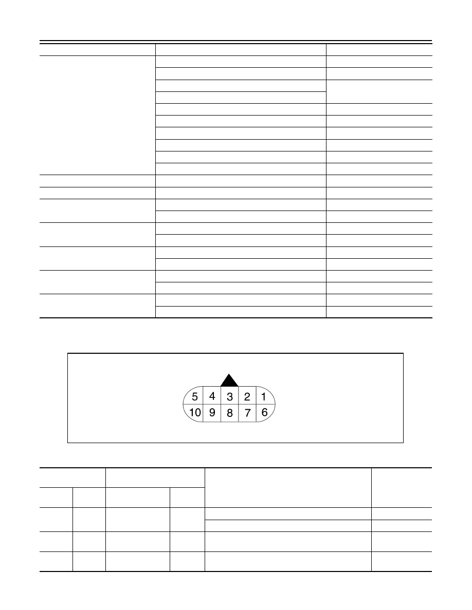
TERMINAL LAYOUT
PHYSICAL VALUES
SLCT LVR POSI
Selector lever in “N” and “P” positions
N/P
Selector lever in “R” position
R
Selector lever in “D” and “DS” positions
D
Selector lever in “M” position: 7GR
Selector lever in “M” position: 6GR
6
Selector lever in “M” position: 5GR
5
Selector lever in “M” position: 4GR
4
Selector lever in “M” position: 3GR
3
Selector lever in “M” position: 2GR
2
Selector lever in “M” position: 1GR
1
GEAR
During driving
1st, 2nd, 3rd, 4th, 5th, 6th, 7th
NEXT GR POSI
During driving
1st, 2nd, 3rd, 4th, 5th, 6th, 7th
SHIFT MODE
Driving with the D position
0 or 3
Driving with the manual mode
4 or 8
D/C PARTS
At 1GR - 2GR shift control
FAIL
Other than the above
NOTFAIL
FR/B PARTS
At control fixed to 1GR
FAIL
Other than the above
NOTFAIL
2346/B PARTS
At control fixed to 1GR
FAIL
Other than the above
NOTFAIL
2346B/DC PARTS
At 2GR - 3GR - 4GR shift control
FAIL
Other than the above
NOTFAIL
Item name
Condition
Value / Status (Approx.)
SCIA1658E
Terminal
(Wire color)
Description
Condition
Value (Approx.)
+
−
Signal name
Input/
Output
1
(Y)
Ground
Power supply
Input
Ignition switch ON
Battery voltage
Ignition switch OFF
0 V
2
(BR)
Ground
Power supply
(Memory back-up)
Input
Always
Battery voltage
3
(L)
—
CAN-H
Input/
Output
—
—
Нет комментариевНе стесняйтесь поделиться с нами вашим ценным мнением.
Текст