Infiniti FX35, FX50 (S51). Manual — part 1408
MWI
CLOCK
MWI-151
< REMOVAL AND INSTALLATION >
C
D
E
F
G
H
I
J
K
L
M
B
A
O
P
CLOCK
Exploded View
INFOID:0000000005524695
REMOVAL
.
DISASSEMBLY
Removal and Installation
INFOID:0000000005524696
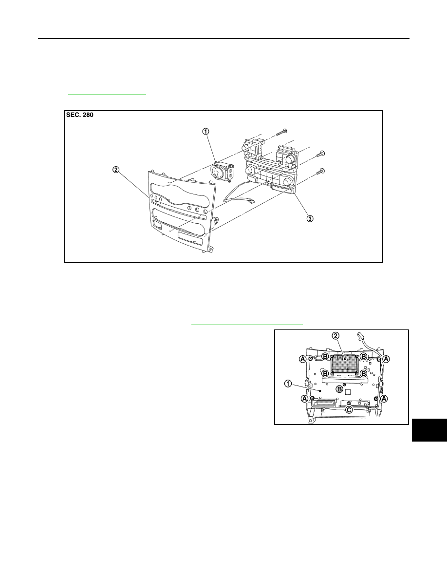
REMOVAL
1.
Remove cluster lid C assembly. Refer to
IP-22, "Removal and Installation"
.
2.
Remove screws (A), (B), (C) and remove clock (2) in conjunction
with preset switch (1) from cluster lid C.
3.
Disengage the tabs to separate clock (2).
INSTALLATION
Install in the reverse order of removal.
NOTE:
Never confuse screws when installing.
JPNIA1102ZZ
1.
Clock
2.
Cluster lid C
3.
Preset switch
JPNIA1103ZZ
PB-1
BRAKES
C
D
E
G
H
I
J
K
L
M
SECTION
PB
A
B
PB
N
O
P
CONTENTS
PARKING BRAKE SYSTEM
PREPARATION . . . . . . . . . . .
PREPARATION . . . . . . . . . . . . ...
Commercial Service Tool . . . . . . . . . . ..
PERIODIC MAINTENANCE . . . . . . ..
PARKING BRAKE SYSTEM . . . . . . . ...
Inspection and Adjustment . . . . . . . . . ....
PARKING BRAKE SHOE . . . . . . . . ...
Adjustment . . . . . . . . . . . . . . . ....
REMOVAL AND INSTALLATION . . . .
PARKING BRAKE CONTROL . . . . . . .
Exploded View . . . . . . . . . . . . . . ..
Removal and Installation . . . . . . . . . . ..
Adjustment . . . . . . . . . . . . . . . ....
PARKING BRAKE SHOE . . . . . . . . ..
Exploded View . . . . . . . . . . . . . . ..
Removal and Installation . . . . . . . . . . ..
Inspection and Adjustment . . . . . . . . . ...
SERVICE DATA AND SPECIFICATIONS
(SDS) . . . . . . . . . . . . . . .
SERVICE DATA AND SPECIFICATIONS
(SDS) . . . . . . . . . . . . . . . . .
Parking Drum Brake . . . . . . . . . . . .
PB-2
< PREPARATION >
PREPARATION
PREPARATION
PREPARATION
Commercial Service Tool
INFOID:0000000005234464
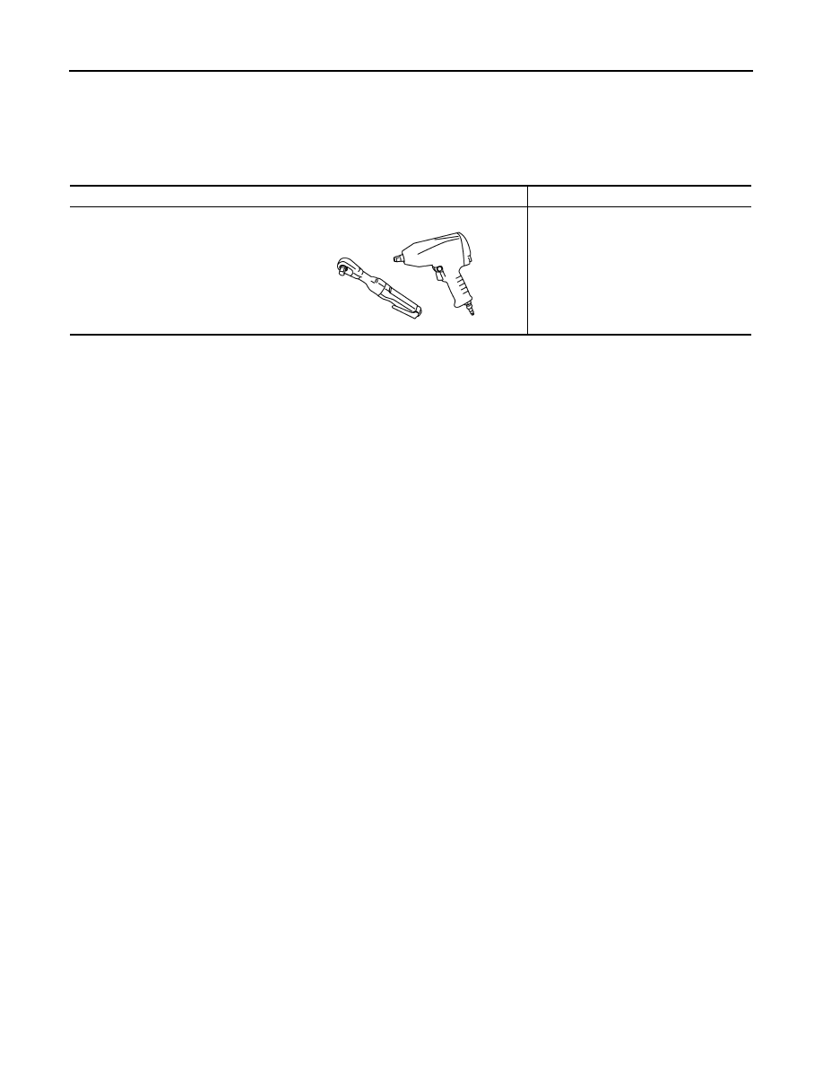
Tool name
Description
Power tool
Loosening bolts and nuts
PBIC0190E
PARKING BRAKE SYSTEM
PB-3
< PERIODIC MAINTENANCE >
C
D
E
G
H
I
J
K
L
M
A
B
PB
N
O
P
PERIODIC MAINTENANCE
PARKING BRAKE SYSTEM
Inspection and Adjustment
INFOID:0000000005234465
INSPECTION
Pedal Stroke
1.
Operate the parking brake pedal with a force of 196 N (20 kg, 44 lb). Check that the pedal stroke is within
the specified number of notches. (Check it by listening to clicks of ratchet.)
2.
When brake warning lamp turns ON, check that the pedal stroke is within the specified number of
notches. (Check it by listening to clicks of ratchet.)
Inspect Components
• Check each component for installation condition such as looseness.
• Check the device assembly for bend, damage and cracks. Replace if necessary.
• Check the cables and equalizer for wear, damage and cracks. Replace if necessary.
• Check the parking brake switch, and replace it if necessary. Refer to
BRC-104, "Diagnosis Procedure"
ADJUSTMENT
1.
Fix the disc rotor using wheel nuts.
2.
Release the parking brake pedal by turning the adjusting nut with a deep socket wrench and loosening the
cable.
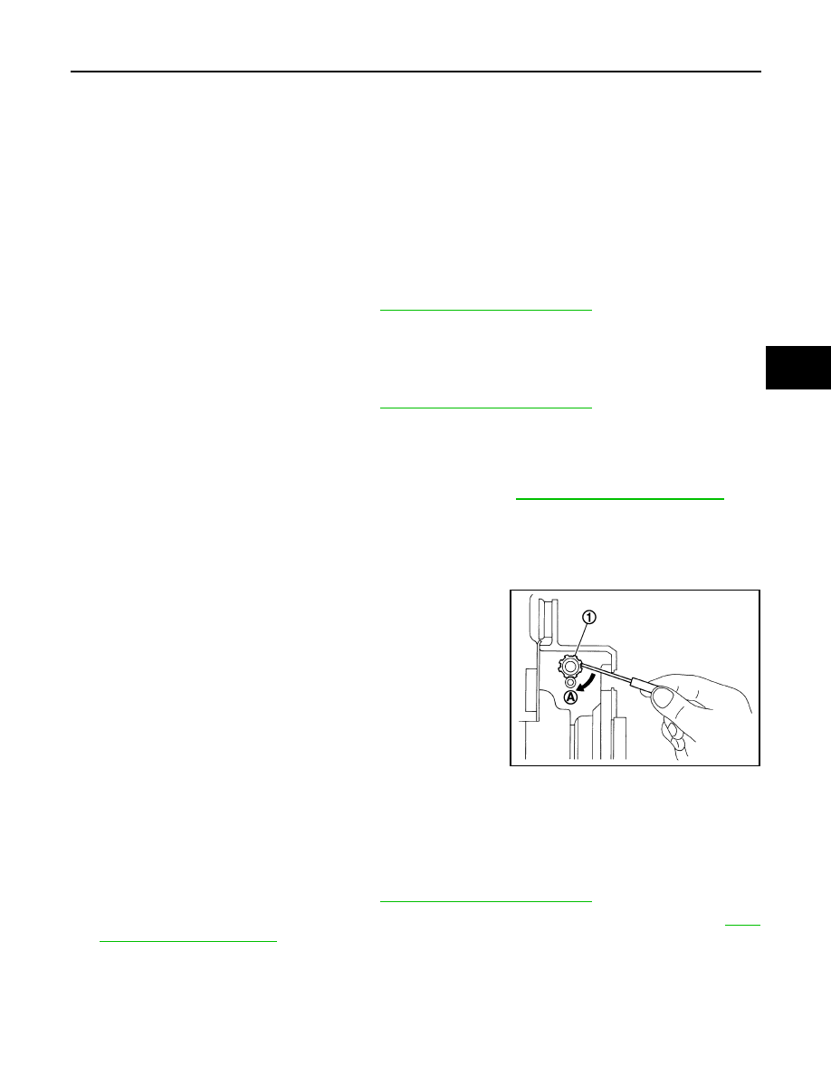
3.
Remove the adjusting hole plug from the disc rotor. Turn the
adjuster (1) in the direction (A) as shown in the figure using a
suitable tool until the disc rotor is locked.
4.
Turn back the adjuster 5 or 6 notches from the locked position.
5.
Rotate the disc rotor to check that there is no drag. Install the
adjusting hole plug.
6.
Adjust the cable with the following procedure.
a.
Operate the parking brake pedal with a force of 490 N (50 kg,
110 lb) for 10 strokes or more.
b.
Adjust the parking brake pedal stroke by turning the adjusting
nut with a deep socket wrench.
CAUTION:
Never reuse the adjusting nut if the nut is removed.
c.
Operate the parking brake pedal with a force of 196 N (20 kg, 44 lb). Check that the pedal stroke is within
the specified number of notches. (Check it by listening to clicks of ratchet.)
d.
Rotate the disc rotor with the parking brake pedal released and check that there is no drag. Refer to
.
Standard
Number of notches
: Refer to
PB-10, "Parking Brake Control"
Standard
Number of notches
: Refer to
PB-10, "Parking Brake Control"
Standard
Number of notches
: Refer to
PB-10, "Parking Brake Control"
JPFIB0002ZZ
Нет комментариевНе стесняйтесь поделиться с нами вашим ценным мнением.
Текст