Infiniti FX35, FX50 (S51). Manual — part 324

CCS-116
< DTC/CIRCUIT DIAGNOSIS >
[ICC (FULL SPEED RANGE)]
C1A39 STEERING ANGLE SENSOR
C1A39 STEERING ANGLE SENSOR
Description
INFOID:0000000005501680
It measures the rotation amount, rotation speed, and rotation direction of steering wheel, and then transmits
them to ICC sensor integrated unit via CAN communication.
DTC Logic
INFOID:0000000005501681
DTC DETECTION LOGIC
NOTE:
If DTC “C1A39” is detected along with DTC “U1000”, first diagnose the DTC “U1000”. Refer to
DTC CONFIRMATION PROCEDURE
1.
PERFORM DTC CONFIRMATION PROCEDURE
1.
Start the engine.
2.
Turn the MAIN switch of ICC system ON.
3.
Perform “All DTC Reading” with CONSULT-III.
4.
Check if the “C1A39” is detected as the current malfunction in “Self Diagnostic Result” of “ICC”.
Is “C1A39” detected as the current malfunction?
YES
>> Refer to
CCS-116, "Diagnosis Procedure"
NO
>> Refer to
GI-36, "Intermittent Incident"
.
Diagnosis Procedure
INFOID:0000000005501682
1.
CHECK SELF-DIAGNOSIS RESULTS
Check if “U1000” is detected other than “C1A39” in “Self Diagnostic Result” of “ICC”.
Is “U1000” detected?
YES
>> Perform the CAN communication system inspection. Repair or replace the malfunctioning parts.
.
NO
>> GO TO 2.
2.
CHECK ABS ACTUATOR AND ELECTRIC UNIT (CONTROL UNIT) SELF-DIAGNOSIS RESULTS
Check if any DTC is detected in “Self Diagnostic Result” of “ABS”.
Is any DTC detected?
YES
>> Perform diagnosis on the detected DTC and repair or replace the malfunctioning parts. Refer to
NO
>> Replace the ICC sensor integrated unit. Refer to
Special Repair Requirement
INFOID:0000000005501683
DESCRIPTION
Perform the action test after adjusting the laser beam aiming of ICC sensor integrated unit when the following
operation is performed.
• Removal and installation of ICC sensor integrated unit
• Replacement of ICC sensor integrated unit
SPECIAL REPAIR REQUIREMENT
1.
LASER BEAM AIMING ADJUSTMENT OF ICC SENSOR INTEGRATED UNIT
DTC
(On board dis-
play)
Trouble diagnosis name
DTC detecting condition
Possible causes
C1A39
(39)
STRG SEN CIR
If the steering angle sensor is malfunction
Steering angle sensor is malfunction

CCS
C1A39 STEERING ANGLE SENSOR
CCS-117
< DTC/CIRCUIT DIAGNOSIS >
[ICC (FULL SPEED RANGE)]
C
D
E
F
G
H
I
J
K
L
M
B
N
P
A
Adjust the laser beam aiming of the ICC sensor integrated unit. Refer to
>> GO TO 2.
2.
CHECK ICC SYSTEM
1.
Erase the “Self Diagnostic Result”, and then perform “All DTC Reading” again after performing the action
test. (Refer to
CCS-18, "ACTION TEST : Description"
2.
Check that the ICC system is normal.
>> WORK END

CCS-118
< DTC/CIRCUIT DIAGNOSIS >
[ICC (FULL SPEED RANGE)]
C1A40 SYSTEM SWITCH CIRCUIT
C1A40 SYSTEM SWITCH CIRCUIT
Description
INFOID:0000000005501684
IBA OFF SWITCH
• The IBA ON/OFF operation is performed by IBA OFF switch.
• The IBA OFF switch signal is input to the brake booster control unit and transmits from the brake booster
control unit to the ICC sensor integrated unit via ITS communication.
DTC Logic
INFOID:0000000005501685
DTC DETECTION LOGIC
NOTE:
If DTC “C1A40” is displayed along with DTC “U1000”, first diagnose the DTC “U1000”. Refer to
DTC CONFIRMATION PROCEDURE
1.
PERFORM DTC CONFIRMATION PROCEDURE
1.
Start the engine and wait for approximately 10 minutes or more.
2.
Perform “All DTC Reading” with CONSULT-III.
3.
Check if the “C1A40” is detected as the current malfunction in “Self Diagnostic Result” of “ICC”.
Is “C1A40” detected as the current malfunction?
YES
>> Refer to
CCS-118, "Diagnosis Procedure"
NO
>> Refer to
GI-36, "Intermittent Incident"
.
Diagnosis Procedure
INFOID:0000000005501686
1.
CHECK SELF-DIAGNOSIS RESULTS
Check if “U1000” is detected other than “C1A40” in “Self Diagnostic Result” of “ICC”.
Is “U1000” detected?
YES
>> Perform the CAN communication system inspection. Repair or replace the malfunctioning parts.
.
NO
>> GO TO 2.
2.
CHECK DATA MONITOR
Check that “IBA SW” operate normally in “DATA MONITOR” of “ICC”.
Is the inspection result normal?
YES
>> Refer to
GI-36, "Intermittent Incident"
.
NO
>> GO TO 3.
3.
CHECK IBA OFF SWITCH
1.
Turn the ignition switch OFF.
2.
Disconnect the IBA OFF switch connector.
3.
Check the IBA OFF switch. Refer to
CCS-119, "Component Inspection (IBA OFF Switch)"
Is the inspection result normal?
YES
>> GO TO 4.
NO
>> Replace the IBA OFF switch.
4.
CHECK HARNESS BETWEEN BRAKE BOOSTER CONTROL UNIT AND IBA OFF SWITCH
1.
Disconnect brake booster control unit connector.
DTC
(On board dis-
play)
Trouble diagnosis
name
DTC detecting condition
Possible causes
C1A40
(40)
SYSTEM SW CIRC
If the IBA OFF switch is stuck to ON
• IBA OFF switch circuit
• IBA OFF switch
• Brake booster control unit
CCS
C1A40 SYSTEM SWITCH CIRCUIT
CCS-119
< DTC/CIRCUIT DIAGNOSIS >
[ICC (FULL SPEED RANGE)]
C
D
E
F
G
H
I
J
K
L
M
B
N
P
A
2.
Check for continuity between the brake booster control unit harness connector and IBA OFF switch har-
ness connector.
3.
Check for continuity between brake booster control unit and ground.
Is the inspection result normal?
YES
>> GO TO 5.
NO
>> Repair the harnesses or connectors.
5.
CHECK IBA OFF SWITCH GROUND CIRCUIT
Check for continuity between IBA OFF switch harness connector and ground.
Is the inspection result normal?
YES
>> GO TO 6.
NO
>> Repair the harnesses or connectors.
6.
CHECK IBA OFF SWITCH SIGNAL
1.
Connect the brake booster control unit connector.
2.
Turn the ignition switch ON.
3.
Check voltage between brake booster control unit harness connector and ground.
Is the inspection result normal?
YES
>> Replace ICC sensor integrated unit. Refer to
NO
>> Replace the brake booster control unit.
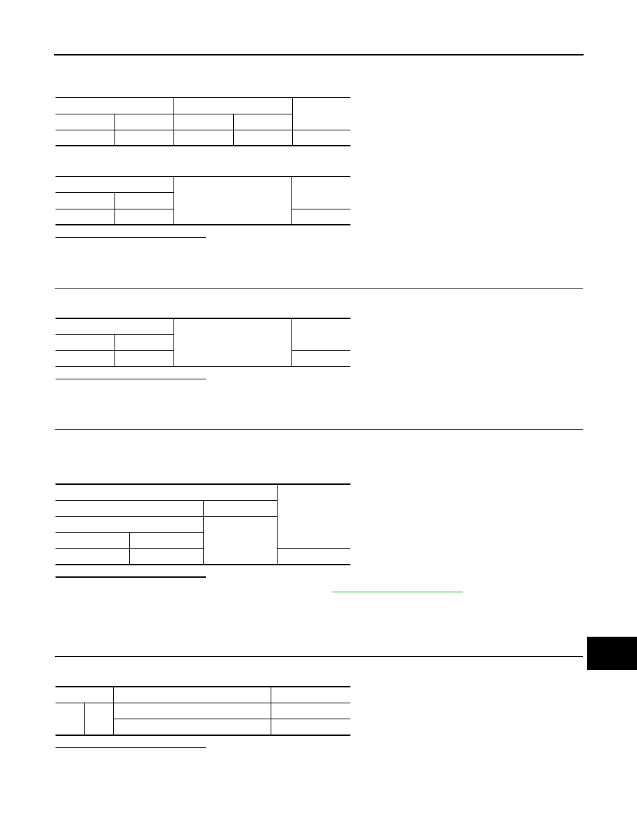
Component Inspection (IBA OFF Switch)
INFOID:0000000005501688
1.
CHECK IBA OFF SWITCH
Check for continuity of IBA OFF switch.
Is the inspection result normal?
YES
>> INSPECTION END
NO
>> Replace the IBA OFF switch.
Brake booster control unit
IBA OFF switch
Continuity
Connector
Terminal
Connector
Terminal
B249
40
M184
7
Existed
Brake booster control unit
Ground
Continuity
Connector
Terminal
B249
40
Not existed
IBA OFF switch
Ground
Continuity
Connector
Terminal
M184
6
Existed
Terminals
Voltage
(Approx.)
(+)
(–)
Brake booster control unit
Ground
Connector
Terminal
B249
40
Battery voltage
Terminal
Condition
Continuity
6
7
When the IBA OFF switch is pressed
Existed
When the IBA OFF switch is released
Not existed
Нет комментариевНе стесняйтесь поделиться с нами вашим ценным мнением.
Текст