Infiniti FX35, FX50 (S51). Manual — part 181
AV
U1247 REAR DISPLAY UNIT
AV-497
< DTC/CIRCUIT DIAGNOSIS >
[NAVIGATION (TWIN MONITOR)]
C
D
E
F
G
H
I
J
K
L
M
B
A
O
P
Is the inspection result normal?
YES
>> GO TO 4.
NO
>> Replace rear display unit.
4.
CHECK SERIAL COMMUNICATION SIGNAL
Check signal between rear display unit harness connector and ground.
Is the inspection result normal?
YES
>> INSPECTION END
NO
>> Replace video distributor.
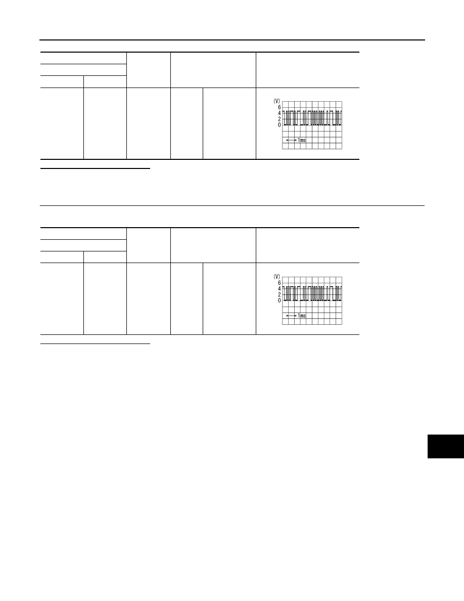
(+)
(
−
)
Condition
Reference value
Rear display unit
Connector
Terminal
B26
9
Ground
Ignition
switch
ON
Rear seat re-
mote controller
operation when
AUX or DVD im-
age is displayed
on rear dis-
played.
PKIB5039J
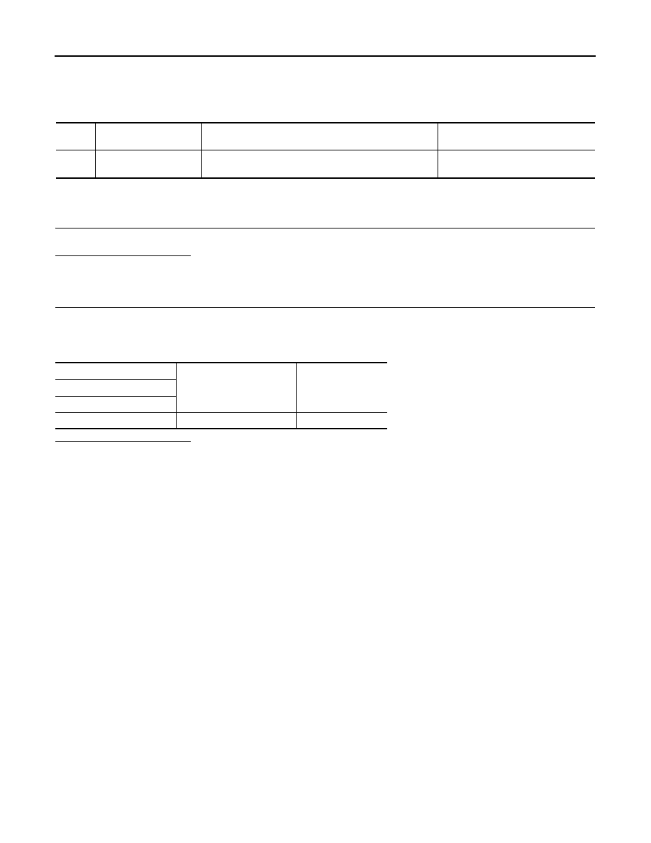
(+)
(
−
)
Condition
Reference value
Rear display unit
Connector
Terminal
B26
10
Ground
Ignition
switch
ON
Rear seat re-
mote controller
operation when
AUX or DVD im-
age is displayed
on rear dis-
played.
PKIB5039J
AV-498
< DTC/CIRCUIT DIAGNOSIS >
[NAVIGATION (TWIN MONITOR)]
U1258 SATELLITE RADIO ANTENNA
U1258 SATELLITE RADIO ANTENNA
DTC Logic
INFOID:0000000005247265
Diagnosis Procedure
INFOID:0000000005247266
1.
SATELLITE RADIO ANTENNA CHECK
Visually check satellite radio antenna and antenna feeder.
Is inspection result normal?
YES
>> GO TO 2.
NO
>> Repair malfunctioning parts.
2.
CHECK AV CONTROL UNIT VOLTAGE
1.
Disconnect satellite radio antenna connector.
2.
Turn ignition switch ON.
3.
Check voltage between AV control unit terminal and ground.
Is inspection result normal?
YES
>> INSPECTION END
NO
>> Replace AV control unit.
DTC
Display contents of
CONSULT-III
DTC Detection Condition
Possible causes
U1258
XM ANTENNA CONN
[U1258]
Satellite radio antenna connection malfunction is detect-
ed.
Satellite radio antenna disconnection
(+)
(
−
)
Voltage
(Approx.)
AV control unit
Terminal
159
Ground
4.0 V

AV
U1263 USB
AV-499
< DTC/CIRCUIT DIAGNOSIS >
[NAVIGATION (TWIN MONITOR)]
C
D
E
F
G
H
I
J
K
L
M
B
A
O
P
U1263 USB
DTC Logic
INFOID:0000000005474840
Diagnosis Procedure
INFOID:0000000005474841
1.
CHECK USB HARNESS
Visually check USB harness.
Is the inspection result normal?
YES
>> Replace AV control unit. Refer to
NO
>> Replace USB harness.
DTC
Display contents of
CONSULT-III
DTC detection condition
Possible malfunction factor
U1263
USB OVERCURRENT
[U1263]
Detection of overcurrent in USB connector.
Check USB harness between the AV
control unit and USB connector.

AV-500
< DTC/CIRCUIT DIAGNOSIS >
[NAVIGATION (TWIN MONITOR)]
U1300 AV COMM CIRCUIT
U1300 AV COMM CIRCUIT
Description
INFOID:0000000005511843
U1300 is indicated when malfunction occurs in communication signal of multi AV system. Indicated simulta-
neously, without fail, with the malfunction of control units connected to AV control unit with communication line.
Determine the possible malfunction cause from the table below.
SELF-DIAGNOSIS RESULTS DISPLAY ITEM
DTC
Display contents of
CONSULT-III
DTC detection condition
Possible malfunction factor
U1300
U1240
• AV COMM CIRCUIT
[U1300]
• SWITCH CONN
[U1240]
When either one of the following items are detected:
• multifunction switch power supply and ground circuits
are malfunctioning.
• AV communication circuits between AV control unit
and multifunction switch are malfunctioning.
• Multifunction switch power supply
and ground circuits.
• AV communication circuits between
AV control unit and multifunction
switch.
U1300
U125B
• AV COMM CIRCUIT
[U1300]
• AROUND CAMERA
CONN [U125B]
around view monitor control unit power supply and
ground circuits are malfunctioning.
Around view monitor control unit power
supply and ground circuits.
U1300
U125C
• AV COMM CIRCUIT
[U1300]
• SONAR CONN
[U125C]
When either one of the following items are detected:
• sonar control unit power supply and ground circuits are
malfunctioning.
• AV communication circuits between AV control unit
and sonar control unit are malfunctioning.
• Sonar control unit power supply and
ground circuits.
• AV communication circuits between
AV control unit and sonar control
unit.
U1300
U1246
U1247
• AV COMM CIRCUIT
[U1300]
• VIDEO DIST CONN
[U1246]
• REAR DISP CONN
[U1247]
When either one of the following items are detected:
• video distributor power supply and ground circuits are
malfunctioning.
• AV communication circuits between around view mon-
itor control unit and video distributor are malfunction-
ing.
• Video distributor power supply and
ground circuits.
• AV communication circuits between
around view monitor control unit and
video distributor.
U1300
U1246
U1247
U125B
• AV COMM CIRVUIT
[U1300]
• VIDEO DIST CONN
[U1246]
• REAR DISP CONN
[1247]
• AROUND CAMERA
CONN [U125B]
AV communication circuits between AV control unit and
around view monitor control unit are malfunctioning.
AV communication circuits between AV
control unit and around view monitor
control unit.
U1300
U1240
U1246
U1247
U125B
• AV COMM CIRCUIT
[U1300]
• SWITCH CONN
[U1240]
• VIDEO DIST CONN
[U1246]
• REAR DISP CONN
[U1247]
• AROUND CAMERA
CONN [U125B]
AV communication circuits between AV control unit and
multifunction switch are malfunctioning.
AV communication circuits between AV
control unit and multifunction switch.
Нет комментариевНе стесняйтесь поделиться с нами вашим ценным мнением.
Текст