Infiniti FX35, FX50 (S51). Manual — part 180
AV
U1243 FRONT DISPLAY UNIT
AV-493
< DTC/CIRCUIT DIAGNOSIS >
[NAVIGATION (TWIN MONITOR)]
C
D
E
F
G
H
I
J
K
L
M
B
A
O
P
U1243 FRONT DISPLAY UNIT
DTC Logic
INFOID:0000000005247256
Diagnosis Procedure
INFOID:0000000005247257
1.
CHECK FRONT DISPLAY UNIT POWER SUPPLY AND GROUND CIRCUITS
Check front display unit power supply and ground circuits. Refer to
AV-510, "FRONT DISPLAY UNIT : Diagno-
Is inspection result normal?
YES
>> GO TO 2.
NO
>> Repair malfunctioning parts.
2.
CHECK CONTINUITY COMMUNICATION CIRCUITS
1.
Turn ignition switch OFF.
2.
Disconnect front display unit connector and AV control unit connector.
3.
Check continuity between front display unit harness connector and AV control unit harness connector.
4.
Check continuity between front display unit harness connector and ground.
Is inspection result normal?
YES
>> GO TO 3.
NO
>> Repair harness or connector.
3.
CHECK COMMUNICATION SIGNAL
1.
Connect front display unit connector and AV control unit connector.
2.
Turn ignition switch ON.
3.
Check signal between front display unit harness connector and ground.
DTC
Display contents of
CONSULT-III
DTC Detection Condition
Possible causes
U1243
FRONT DISP CONN
[U1243]
When either one of the following items is detected.
• front display unit power supply and ground circuit mal-
function is detected.
• malfunction is detected in communication circuits be-
tween front display unit and AV control unit.
• Front display unit power supply and
ground circuit.
• Communication circuits between
front display unit and AV control
unit.
Front display unit
AV control unit
Continuity
Connector
Terminals
Connector
Terminals
M195
9
M210
89
Existed
10
73
Front display unit
Ground
Continuity
Connector
Terminals
M195
9
Not existed
10
AV-494
< DTC/CIRCUIT DIAGNOSIS >
[NAVIGATION (TWIN MONITOR)]
U1243 FRONT DISPLAY UNIT
Is inspection result normal?
YES
>> GO TO 4.
NO
>> Replace AV control unit.
4.
CHECK COMMUNICATION SIGNAL
Check signal between front display unit harness connector and ground.
Is inspection result normal?
YES
>> INSPECTION END
NO
>> Replace front display unit.
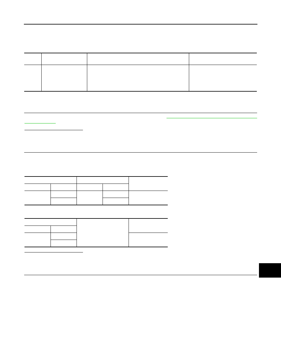
(+)
(
−
)
Condition
Reference value
Front display unit
Connector
Terminal
M195
9
Ground
When adjusting display bright-
ness.
PKIB5039J
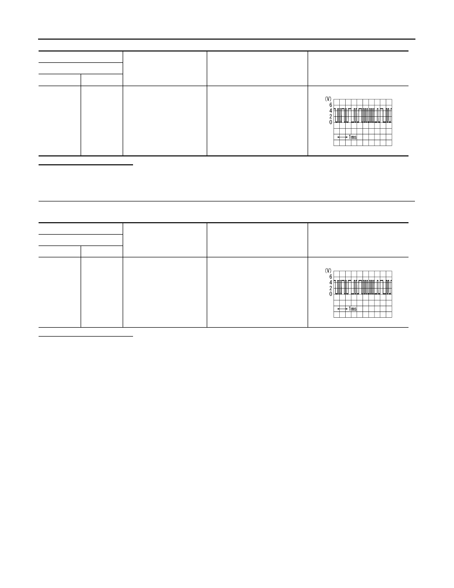
(+)
(
−
)
Condition
Reference value
Front display unit
Connector
Terminal
M195
10
Ground
When adjusting display bright-
ness.
PKIB5039J
AV
U1244 GPS ANTENNA
AV-495
< DTC/CIRCUIT DIAGNOSIS >
[NAVIGATION (TWIN MONITOR)]
C
D
E
F
G
H
I
J
K
L
M
B
A
O
P
U1244 GPS ANTENNA
DTC Logic
INFOID:0000000005247259
Diagnosis Procedure
INFOID:0000000005247260
1.
GPS ANTENNA CHECK
Visually check GPS antenna and antenna feeder.
Is inspection result normal?
YES
>> GO TO 2.
NO
>> Repair malfunctioning parts.
2.
CHECK AV CONTROL UNIT VOLTAGE
1.
Disconnect GPS antenna connector.
2.
Turn ignition switch ON.
3.
Check voltage between AV control unit terminal and ground.
Is inspection result normal?
YES
>> INSPECTION END
NO
>> Replace AV control unit.
DTC
Display contents of
CONSULT-III
DTC Detection Condition
Possible causes
U1244
GPS ANTENNA CONN
[U1244]
GPS antenna connection malfunction is detected.
GPS antenna disconnection
(+)
(
−
)
Voltage
(Approx.)
AV control unit
Terminal
153
Ground
5.0 V
AV-496
< DTC/CIRCUIT DIAGNOSIS >
[NAVIGATION (TWIN MONITOR)]
U1247 REAR DISPLAY UNIT
U1247 REAR DISPLAY UNIT
DTC Logic
INFOID:0000000005247262
Diagnosis Procedure
INFOID:0000000005247263
1.
CHECK REAR DISPLAY UNIT POWER SUPPLY AND GROUND CIRCUIT
Check rear display unit power supply and ground circuits. Refer to
AV-511, "REAR DISPLAY UNIT : Diagnosis
.
Is the inspection result normal?
YES
>> GO TO 2.
NO
>> Repair malfunctioning parts.
2.
CHECK CONTINUITY SERIAL COMMUNICATION CIRCUIT
1.
Turn ignition switch OFF.
2.
Disconnect rear display unit connector and video distributor connector.
3.
Check continuity between rear display unit harness connector and video distributor harness connector.
4.
Check continuity between rear display unit harness connector and ground.
Is the inspection result normal?
YES
>> GO TO 3.
NO
>> Repair harness or connector.
3.
CHECK SERIAL COMMUNICATION SIGNAL
1.
Connect rear display unit connector and video distributor connector.
2.
Turn ignition switch ON.
3.
Check signal between rear display unit harness connector and ground.
DTC
Display contents of
CONSULT-III
DTC Detection Condition
Possible causes
U1247
REAR DISP CONN
[U1247]
When either one of the following items is detected:
• rear display unit power supply and ground circuits are
malfunctioning.
• serial communication circuits between video distributor
and rear display unit are malfunctioning.
• Rear display unit power supply and
ground circuits.
• Serial communication circuits be-
tween AV control unit and rear dis-
play unit.
Rear display unit
Video distributor
Continuity
Connector
Terminals
Connector
Terminals
B26
9
M97
39
Existed
10
40
Rear display unit
Ground
Continuity
Connector
Terminals
B26
9
Not existed
10
Нет комментариевНе стесняйтесь поделиться с нами вашим ценным мнением.
Текст