Infiniti FX35, FX50 (S51). Manual — part 1578

RSU-10
< REMOVAL AND INSTALLATION >
REAR SHOCK ABSORBER
REAR SHOCK ABSORBER
Exploded View
INFOID:0000000005249854
WITHOUT CONTINUOUS DAMPING CONTROL
WITH CONTINUOUS DAMPING CONTROL
Removal and Installation
INFOID:0000000005249855
REMOVAL
1.
Remove tires with power tool.
2.
Remove shock absorber actuator harness connector (with Continuous Damping Control).
1.
Cap
2.
Mounting seal
3.
Shock absorber mounting bracket
4.
Bound bumper cover
5.
Shock absorber
6.
Front lower link
Refer to
for symbols in the figure.
JPEIB0115GB
1.
Cap
2.
Mounting seal
3.
Shock absorber mounting bracket
4.
Bound bumper cover
5.
Shock absorber
6.
Front lower link
Refer to
for symbols in the figure.
JPEIB0130GB
REAR SHOCK ABSORBER
RSU-11
< REMOVAL AND INSTALLATION >
C
D
F
G
H
I
J
K
L
M
A
B
RSU
N
O
P
3.
Set suitable jack under axle assembly to relieve the coil spring tension.
4.
Remove shock absorber (lower side) with power tool.
5.
Gradually lower the jack to remove it from rear lower link.
6.
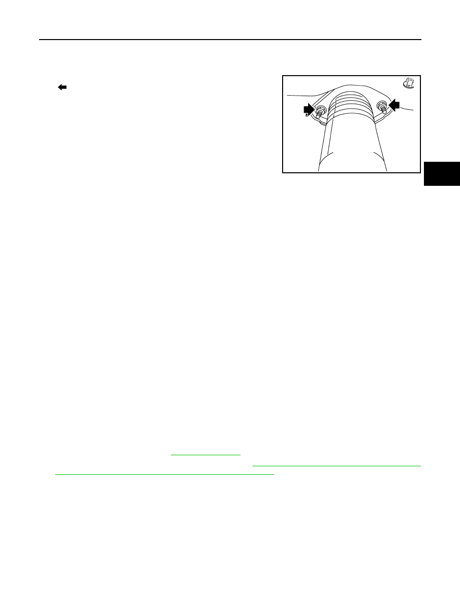
Remove shock absorber assembly mounting nuts (upper side)
(
), and then remove shock absorber assembly.
INSTALLATION
Note the following, and install in the reverse order of removal.
• Perform final tightening of bolts and nuts at the shock absorber lower side (rubber bushing), under unladen
conditions with tires on level ground.
Disassembly and Assembly
INFOID:0000000005249856
DISASSEMBLY
CAUTION:
Never damage shock absorber piston rod when removing components from shock absorber.
1.
Remove cap from mounting bracket
2.
Wrap a shop cloth around lower side of shock absorber and fix it with a vise.
CAUTION:
Never set the cylindrical part of shock absorber with a vise.
3.
Secure the piston rod tip so that piston rod does not turn, and remove piston rod lock nut.
4.
Remove mounting seal, mounting bracket and bound bumper cover from shock absorber.
ASSEMBLY
Install in the reverse order of disassembly.
Inspection
INFOID:0000000005249857
INSPECTION AFTER REMOVAL
Check the following items, and replace the parts if necessary.
• Shock absorber assembly for deformation, cracks, damage.
• Welded and sealed areas for oil leakage.
INSPECTION AFTER INSTALLATION
1.
Check shock absorber actuator harness connector for proper connection (with Continuous Damping Con-
trol).
2.
Check wheel alignment. Refer to
3.
Adjust neutral position of steering angle sensor. Refer to
BRC-9, "ADJUSTMENT OF STEERING ANGLE
SENSOR NEUTRAL POSITION : Special Repair Requirement"
.
INSPECTION AFTER DISASSEMBLY
Bound Bumper and Bushing
Check bound bumper cover and bushing for cracks and damage. Replace it if necessary.
Shock Absorber
Check the following items, and replace the part if necessary.
• Shock absorber for deformation, cracks, and other damage.
• Piston rod for damage, uneven wear, and distortion.
INSPECTION AFTER ASSEMBLY
JPEIB0100ZZ
RSU-12
< REMOVAL AND INSTALLATION >
REAR SHOCK ABSORBER
Make sure piston rod on shock absorber is not damaged when attaching components to shock absorber.
Disposal
INFOID:0000000005249858
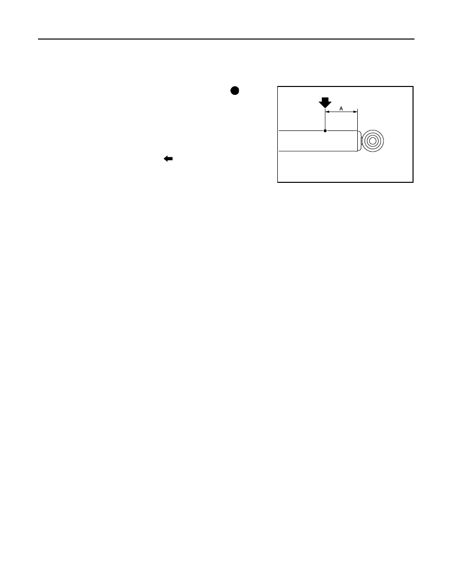
1.
Set shock absorber horizontally with the piston rod fully extended.
2.
Drill 2 – 3 mm (0.08 – 0.12 in) hole at the position (
) from top
as shown in the figure to release gas gradually.
CAUTION:
• Wear eye protection (safety glasses).
• Wear gloves.
• Be careful with metal chips or oil blown out by the com-
pressed gas.
NOTE:
• Drill vertically in this direction (
).
• Directly to the outer tube avoiding brackets.
• The gas is clear, colorless, odorless, and harmless.
3.
Position the drilled hole downward and drain oil by moving the piston rod several times.
CAUTION:
Dispose of drained oil according to the law and local regulations.
A
: 20 – 30 mm (0.79 – 1.18 in)
JPEIA0161ZZ
SUSPENSION ARM
RSU-13
< REMOVAL AND INSTALLATION >
C
D
F
G
H
I
J
K
L
M
A
B
RSU
N
O
P
SUSPENSION ARM
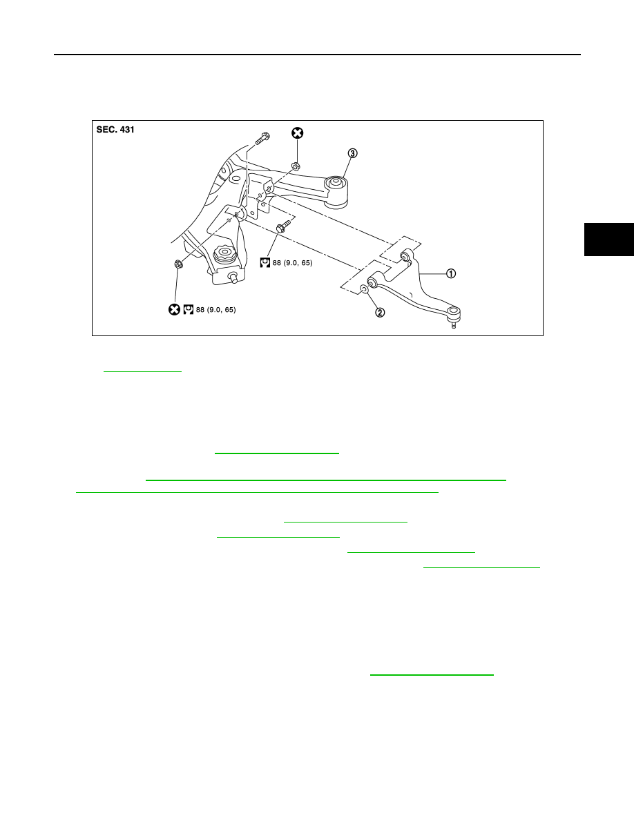
Exploded View
INFOID:0000000005249859
Removal and Installation
INFOID:0000000005249860
REMOVAL
1.
Remove tire with power tool.
2.
Remove radius rod. Refer to
3.
Remove caliper assembly mounting bolts. Hang caliper assembly in a place where it will not interfere with
work. Refer to
BR-56, "BRAKE CALIPER ASSEMBLY (1 PISTON TYPE) : Exploded View"
(1 piston type),
BR-60, "BRAKE CALIPER ASSEMBLY (2 PISTON TYPE) : Exploded View"
(2 piston type).
4.
Set suitable jack under axle assembly to relieve the coil spring tension.
5.
Remove stabilizer connecting rod. Refer to
.
6.
Remove drive shaft. Refer to
.
7.
Remove height sensor (with xenon head lamp). Refer to
.
8.
Remove cotter pin of suspension arm ball joint, and loosen nut. Refer to
.
9.
Remove suspension arm mounting bolts and nuts (rear suspension member side).
10. Use the ball joint remover to remove suspension arm from axle housing. Be careful not to damage ball
joint boot.
CAUTION:
Tighten temporarily mounting nut to prevent damage to threads and to prevent ball joint remover
from coming off.
11. Remove suspension arm.
12. Remove stabilizer connecting rod mounting bracket. Refer to
INSTALLATION
Note the following and, install in the reverse order of removal.
• Perform final tightening of rear suspension member installation position (rubber bussing), under unladen
conditions with tires on level ground.
Inspection
INFOID:0000000005249861
INSPECTION AFTER REMOVAL
1.
Suspension arm
2.
Stopper rubber
3.
Rear suspension member
for symbols in the figure.
JPEIB0193GB
Нет комментариевНе стесняйтесь поделиться с нами вашим ценным мнением.
Текст