Infiniti FX35, FX50 (S51). Manual — part 1605
DIAGNOSIS AND REPAIR WORK FLOW
SCS-5
< BASIC INSPECTION >
C
D
F
G
H
I
J
K
L
M
A
B
SCS
N
O
P
>> GO TO 9.
9.
FINAL CHECK
Perform the “DTC confirmation procedure” or “Component Inspection” to check that the repair is correctly per-
formed. Check that malfunctions are not reproduced when obtaining the malfunction information from the cus-
tomer, referring to the symptom inspection result in step 3 or 4.
Is the check result normal?
YES
>> Trouble diagnosis is completed.
NO-1
>> The DTC is reproduced. GO TO 7.
NO-2
>> The symptom is reproduced. GO TO 6.
SCS-6
< SYSTEM DESCRIPTION >
CONTINUOUS DAMPING CONTROL SYSTEM
SYSTEM DESCRIPTION
CONTINUOUS DAMPING CONTROL SYSTEM
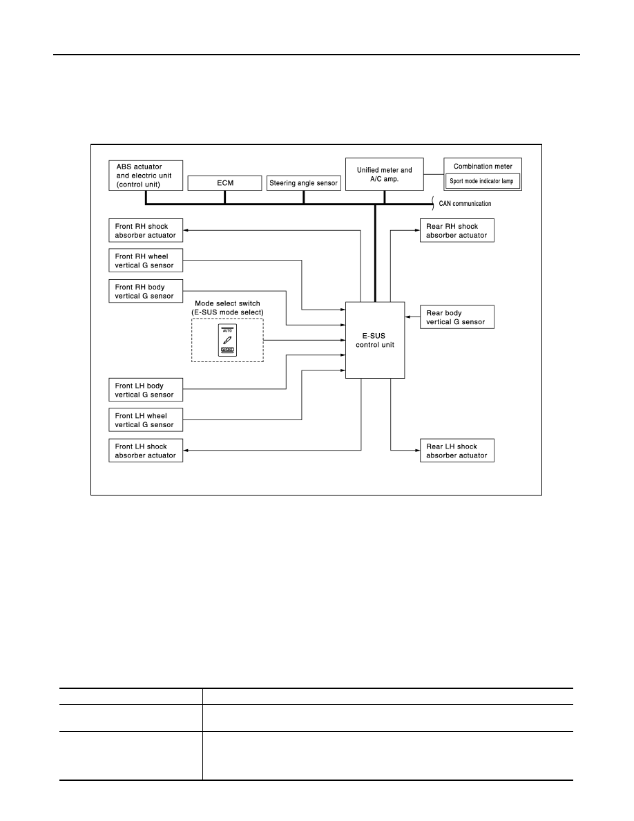
System Diagram
INFOID:0000000005236138
System Description
INFOID:0000000005236139
Description
• The Continuous Damping Control system mainly consists of the components such as the E-SUS control
unit, front body vertical G sensor, front wheel vertical G sensor, rear body vertical G sensor, and shock
absorber actuators on each wheel.
• It calculates the command values to be transmitted to the shock absorber actuator on each wheel based on
the information from ECM, ABS actuator and electric unit (control unit) and steering angle sensor via CAN
communication and information from the front body vertical G sensor, front wheel vertical G sensor and rear
body vertical G sensor.
• The shock absorber actuator on each wheel controls the damping force based on the command values cal-
culated by E-SUS control unit.
• Can perform the self-diagnosis with CONSULT-III.
• Communicates the signal from each control unit via CAN communication.
JSEIA0014GB
Control unit
Signal status
Steering angle sensor
Transmits mainly the following signals to E-SUS control unit via CAN communication.
• Steering angle signal
ABS actuator and electric unit
(control unit)
Transmits mainly the following signals to E-SUS control unit via CAN communication.
• Vehicle speed signal
• Brake pressure control signal
• Stop lamp switch signal
CONTINUOUS DAMPING CONTROL SYSTEM
SCS-7
< SYSTEM DESCRIPTION >
C
D
F
G
H
I
J
K
L
M
A
B
SCS
N
O
P
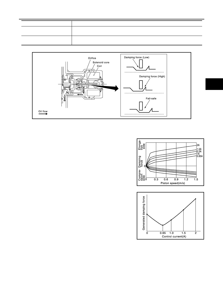
Operation principle
Controls damping force by changing the oil passage cross section area through control of orifice by solenoid
core activation.
Operation characteristics
• Changes the damping force control by switching the switch (AUTO
mode or SPORT mode).
• Changes the damping force depending on the output current to the
shock absorber actuators.
ECM
Transmits mainly the following signals to E-SUS control unit via CAN communication.
• Requested torque signal
Unified meter and A/C amp.
Transmits mainly the following signals from E-SUS control unit via CAN communication.
• Sport mode indicator lamp signal
Control unit
Signal status
JSEIA0017GB
JSEIA0015GB
JSEIA0016GB
SCS-8
< SYSTEM DESCRIPTION >
CONTINUOUS DAMPING CONTROL SYSTEM
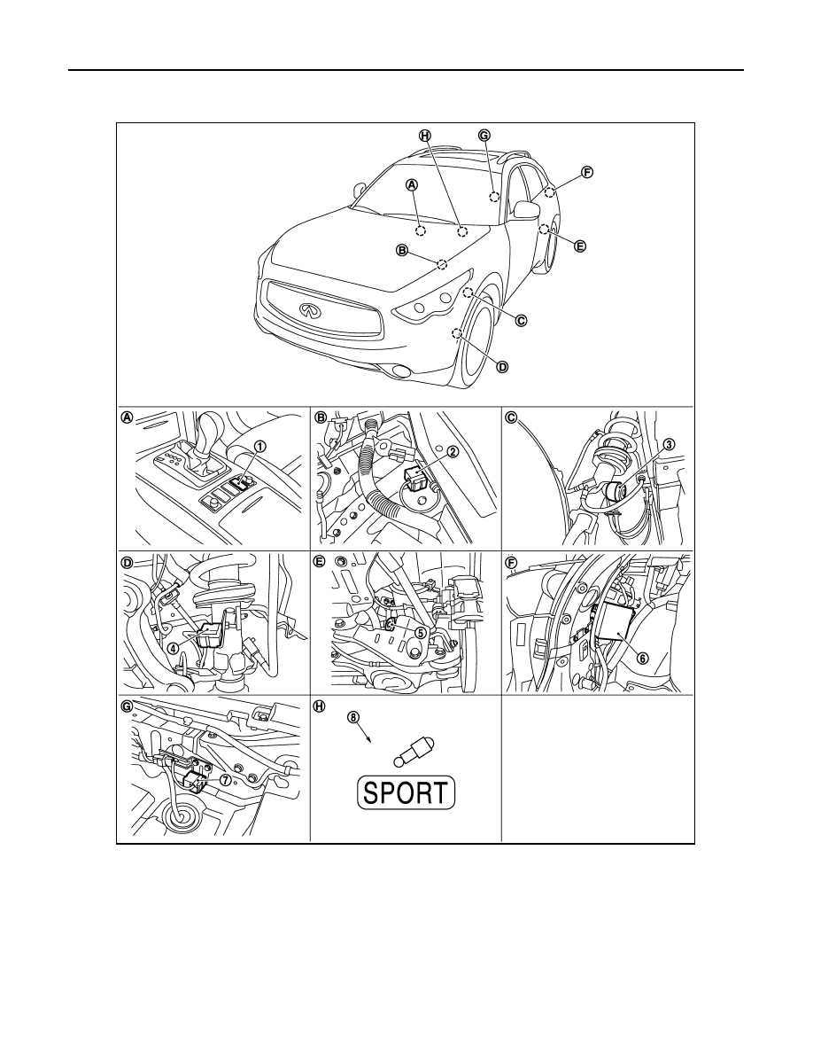
Component Parts Location
INFOID:0000000005236140
1.
Mode select switch
(E-SUS mode select)
2.
Front body vertical G sensor
(left and right)
3.
Front shock absorber actuator
(left and right)
4.
Front wheel vertical G sensor
(left and right)
5.
Rear shock absorber actuator
(left and right)
6.
E-SUS control unit
7.
Rear body vertical G sensor
8.
Sport mode indicator lamp
A.
Center console panel
B.
Strut tower
C.
Front strut
D.
Front strut side
E.
Rear strut
F.
Trunk room left back
G.
Trunk floor
H.
Combination meter
JSEIA0018ZZ
Нет комментариевНе стесняйтесь поделиться с нами вашим ценным мнением.
Текст