Infiniti FX35, FX50 (S51). Manual — part 427
CCS-528
< ECU DIAGNOSIS INFORMATION >
[LDW & LDP]
ABS ACTUATOR AND ELECTRIC UNIT (CONTROL UNIT)
Fail-Safe
INFOID:0000000005681344
ABS, EBD SYSTEM
If ABS malfunction electrically, ABS warning lamp, VDC OFF indicator lamp, SLIP indicator lamp will turn on. If
EBD malfunction electrically, brake warning lamp, ABS warning lamp, VDC OFF indicator lamp and SLIP indi-
cator lamp will turn on. Simultaneously, the VDC/TCS/ABS become one of the following conditions of the fail-
safe function.
JCFWA0310GB
CCS
ABS ACTUATOR AND ELECTRIC UNIT (CONTROL UNIT)
CCS-529
< ECU DIAGNOSIS INFORMATION >
[LDW & LDP]
C
D
E
F
G
H
I
J
K
L
M
B
N
P
A
• For malfunction of ABS, only the EBD is activated and the condition of vehicle is the same condition of vehi-
cles without TCS/ABS system.
NOTE:
ABS self-diagnosis sound may be heard. That is a normal condition because a self-diagnosis for “Ignition
switch ON” and “The first starting” are being performed.
• For malfunction of EBD, EBD and ABS become inoperative, and the condition of vehicle is the same as the
condition of vehicles without TCS/ABS, EBD system.
VDC/TCS
If VDC/TCS/ABS system malfunction electrically, VDC OFF indicator lamp, SLIP indicator lamp are turned on,
and the condition of vehicle is the same as the condition of vehicles without VDC/TCS control.
CAUTION:
If the Fail-Safe function is activated, then perform self-diagnosis for “ABS” with CONSULT-III.
LDW/LDP SYSTEM
• In case of malfunction in the LDW/LDP system, lane departure warning lamp is turned ON, and the condition
of vehicle is the same as the condition of vehicles without LDW/LDP control.
• In case of malfunction in the VDC/TCS/ABS system, lane departure warning lamp is turned ON, and the
condition of vehicle is the same as the condition of vehicles without LDW/LDP control.
DTC Index
INFOID:0000000005681345
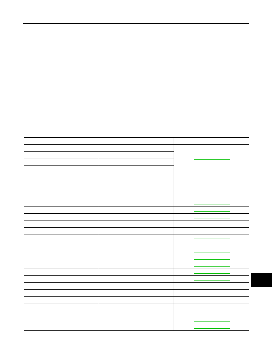
DTC
Items (CONSULT screen terms)
Reference
C1101
RR RH SENSOR-1
C1102
RR LH SENSOR-1
C1103
FR RH SENSOR-1
C1104
FR LH SENSOR-1
C1105
RR RH SENSOR-2
C1106
RR LH SENSOR-2
C1107
FR RH SENSOR-2
C1108
FR LH SENSOR-2
C1109
BATTERY VOLTAGE [ABNORMAL]
C1110
CONTROLLER FAILURE
C1111
PUMP MOTOR
C1114
MAIN RELAY
C1115
ABS SENSOR [ABNORMAL SIGNAL]
C1116
STOP LAMP SW
C1120
FR LH IN ABS SOL
C1121
FR LH OUT ABS SOL
C1122
FR RH IN ABS SOL
C1123
FR RH OUT ABS SOL
C1124
RR LH IN ABS SOL
C1125
RR LH OUT ABS SOL
C1126
RR RH IN ABS SOL
C1127
RR RH OUT ABS SOL
C1130
ENGINE SIGNAL 1
C1137
RAS CIRCUIT (Note 1)
C1142
PRESS SEN CIRCUIT
C1143
ST ANG SEN CIRCUIT
C1144
ST ANG SEN SIGNAL
CCS-530
< ECU DIAGNOSIS INFORMATION >
[LDW & LDP]
ABS ACTUATOR AND ELECTRIC UNIT (CONTROL UNIT)
NOTE:
1: With RAS models
2: With ICC models
3: With VK50VE models
4: With LDP models
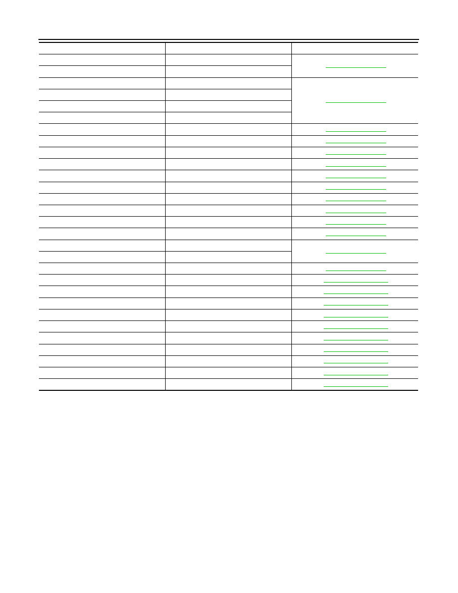
C1145
YAW RATE SENSOR
C1146
SIDE G-SEN CIRCUIT
C1147
USV LINE [FL-RR]
C1148
USV LINE [FR-RL]
C1149
HSV LINE [FL-RR]
C1150
HSV LINE [FR-RL]
C1153
EMERGENCY BRAKE
C1154
PNP POSI SIG
C1155
BR FLUID LEVEL LOW
C1156
ST ANG SEN COM CIR
C1170
VARIANT CORDING
C1185
ACC CONT (Note 2)
C1197
VACUUM SENSOR (Note 3)
C1198
VACUUM SEN CIR (Note 3)
C1199
BRAKE BOOSTER (Note 3)
C119A
VACUUM SEN VOLT (Note 3)
U1000
CAN COMM CIRCUIT
U1002
SYSTEM COMM
U1100
ACC COMM CIRCUIT (Note 2)
C1B00
LDP) CAMERA MALF (Note 4)
C1B04
LDP) ICC STG SW MALF (Note 4)
C1B05
LDP) APP SEN MALF (Note 4)
C1B06
LDP) TCM MALF (Note 4)
U0100
LDP) ECM CAN CIR2 (Note 4)
U0101
LDP) TCM CAM CAN CIR2 (Note 4)
U0104
LDP) ICC CAM CAN CIR2 (Note 4)
U0405
LDP) ICC CAM CAN CIR1 (Note 4)
U1500
LDP) CAM CAN CIR1 (Note 4)
U1501
LDP) CAM CAN CIR2 (Note 4)
DTC
Items (CONSULT screen terms)
Reference

CCS
LDW & LDP SYSTEM SYMPTOMS
CCS-531
< SYMPTOM DIAGNOSIS >
[LDW & LDP]
C
D
E
F
G
H
I
J
K
L
M
B
N
P
A
SYMPTOM DIAGNOSIS
LDW & LDP SYSTEM SYMPTOMS
Symptom Table
INFOID:0000000005502130
CAUTION:
Perform the self-diagnosis with CONSULT-III before the symptom diagnosis. Perform the trouble diag-
nosis if any DTC is detected.
Symptom
Possible cause
Inspection item/Reference page
Indicator/warning lamps do not il-
luminate when ignition switch
OFF
⇒
ON.
Lane departure warning
lamp (Yellow) does not illumi-
nate.
• Lane departure warning lamp
signal (CAN)
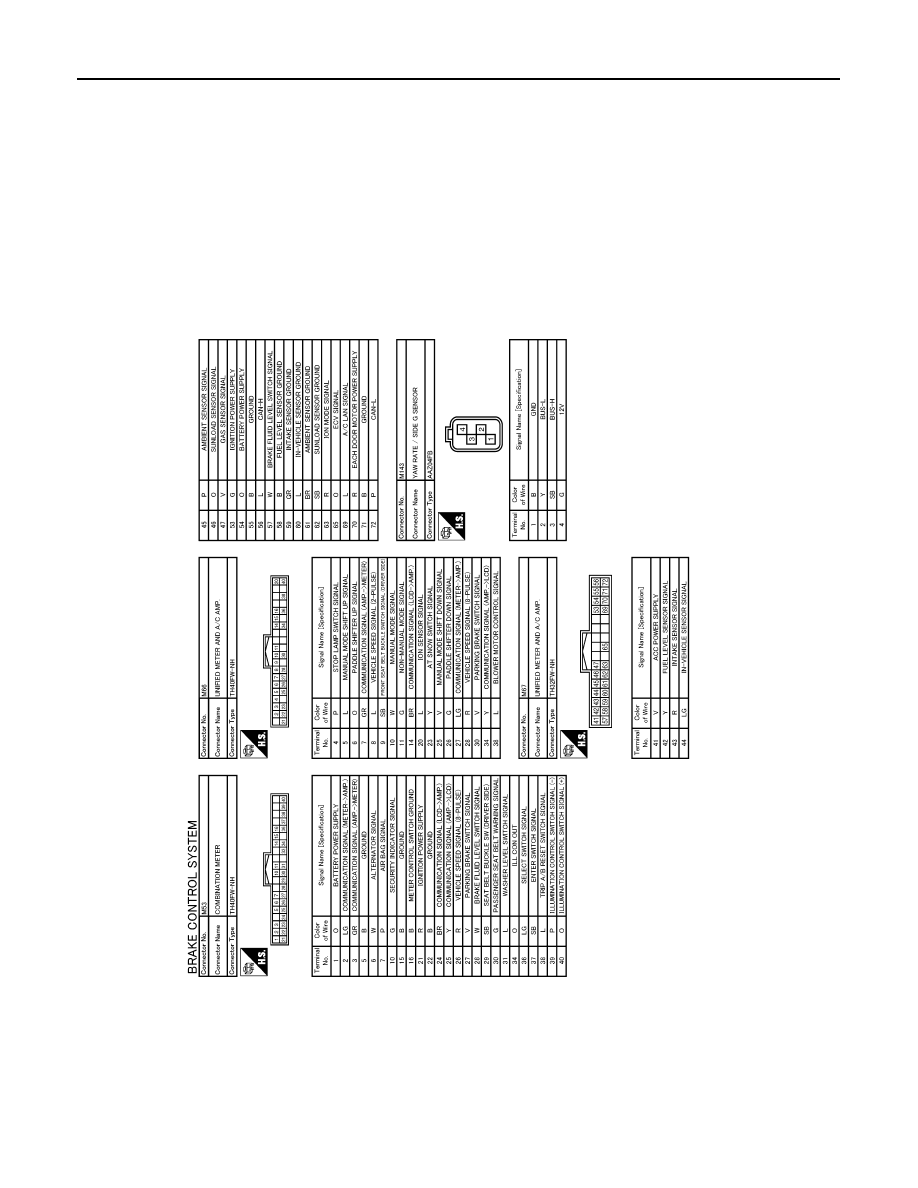
- Unified meter and A/C amp.
- Lane camera unit
• Lane departure warning lamp
(Combination meter)
• LANE CAMERA Active test
“LANE DEPARTURE W/L”
• METER/M&A Data monitor
“LANE W/L”
LDP ON indicator lamp
(Green) does not illuminate.
• LDP ON indicator lamp signal
(CAN)
- Unified meter and A/C amp.
- Lane camera unit
• LDP ON indicator lamp
(Combination meter)
• LANE CAMERA Active test
“LDP ON IND”
• METER/M&A Data monitor
“LDP IND”
LDW ON indicator (on the
LDW switch) does not illumi-
nate.
• Harness between lane cam-
era unit and LDW switch.
• LDW ON indicator
(LDW switch)
• Lane camera unit
LDW ON indicator circuit
Lane departure warning
lamp (Yellow) and LDP ON
indicator lamp (Green) do not
illuminate.
• Combination meter
• Unified meter and A/C amp.
• Lane camera unit
—
All of indicator/warning
lamps do not illuminate;
• Lane departure warning
lamp (Yellow)
• LDP ON indicator lamp
(Green)
• LDW ON indicator
• Power supply and ground cir-
cuit of lane camera unit
• Lane camera unit
Power supply and ground circuit
of lane camera unit
LDW system is not activated.
(Indicator/warning lamps illumi-
nate when ignition switch OFF
⇒
ON.)
LDW ON indicator is not
turned ON
⇔
OFF when op-
erating LDW switch.
• Harness between lane cam-
era unit and LDW switch.
• Harness between LDW
switch and ground.
• Lane camera unit
LDW switch circuit
Lane departure warning
buzzer is not sounding.
(Lane departure warning
lamp is activated.)
• Harness between the fuse
and lane departure warning
buzzer.
• Harness between lane cam-
era unit and lane departure
warning buzzer.
• Harness between lane depar-
ture warning buzzer and
ground.
• Lane departure warning buzz-
er
• Lane camera unit
Lane departure warning buzzer
circuit
Lane departure warning
lamp is not activated.
(Lane departure warning
buzzer is sounding.)
Lane camera unit
—
Нет комментариевНе стесняйтесь поделиться с нами вашим ценным мнением.
Текст