Infiniti FX35, FX50 (S51). Manual — part 1077
FAX-6
< REMOVAL AND INSTALLATION >
[2WD]
FRONT WHEEL HUB AND KNUCKLE
REMOVAL AND INSTALLATION
FRONT WHEEL HUB AND KNUCKLE
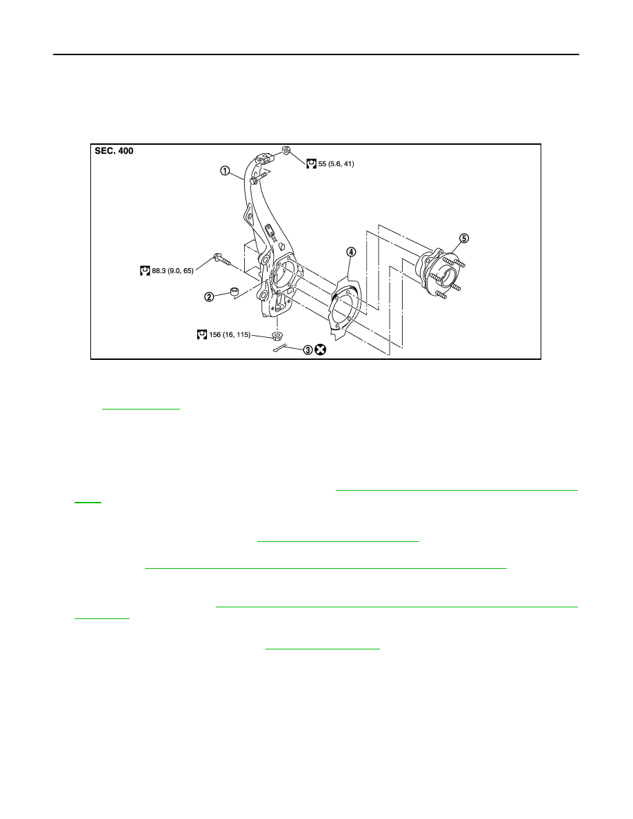
Exploded View
INFOID:0000000005248975
Removal and Installation
INFOID:0000000005248976
REMOVAL
1.
Remove tires with power tool.
2.
Remove wheel sensor and sensor harness. Refer to
BRC-131, "FRONT WHEEL SENSOR : Exploded
.
CAUTION:
Never pull on wheel sensor harness.
3.
Remove brake hose bracket. Refer to
BR-20, "FRONT : Exploded View"
.
4.
Remove caliper assembly with power tool. Hang caliper assembly in a place where it will not interfere with
work. Refer to
BR-43, "BRAKE CALIPER ASSEMBLY (2 PISTON TYPE) : Exploded View"
.
CAUTION:
Never depress brake pedal while brake caliper is removed.
5.
Remove disc rotor. Refer to
BR-44, "BRAKE CALIPER ASSEMBLY (2 PISTON TYPE) : Removal and
.
6.
Remove wheel hub and bearing assembly, and then remove splash guard.
7.
Remove steering outer socket. Refer to
8.
Remove cotter pin of transverse link and steering knuckle, and then loosen nut.
9.
Separate steering knuckle from upper link.
10. Separate steering knuckle from transverse link so as not to damage ball joint boot using the ball joint
remover, and remove steering knuckle.
CAUTION:
Temporarily tighten the nut to prevent damage to threads and to prevent the ball joint remover
from suddenly coming off.
INSTALLATION
Note the following, and install in the reverse order of the removal.
1.
Steering knuckle
2.
Ball seat
3.
Cotter pin
4.
Splash guard
5.
Wheel hub and bearing assembly
Refer to
for symbols in the figure.
JPDIF0189GB

FRONT WHEEL HUB AND KNUCKLE
FAX-7
< REMOVAL AND INSTALLATION >
[2WD]
C
E
F
G
H
I
J
K
L
M
A
B
FAX
N
O
P
• Perform the final tightening of each of parts under unladen conditions, which were removed when removing
wheel hub and bearing assembly and steering knuckle.
• Never reuse cotter pin.
Inspection
INFOID:0000000005248977
INSPECTION AFTER REMOVAL
Check components for deformation, cracks, and other damage. Replace it if necessary.
Ball Joint Inspection
Check boots of transverse link and steering outer socket ball joint for breakage, axial play, and torque. Refer to
INSPECTION AFTER INSTALLATION
1.
Check wheel sensor harness for proper connection. Refer to
BRC-131, "FRONT WHEEL SENSOR :
.
2.
Check the wheel alignment. Refer to
.
3.
Adjust neutral position of steering angle sensor. Refer to
BRC-9, "ADJUSTMENT OF STEERING ANGLE
SENSOR NEUTRAL POSITION : Special Repair Requirement"
.
FAX-8
< SERVICE DATA AND SPECIFICATIONS (SDS)
[2WD]
SERVICE DATA AND SPECIFICATIONS (SDS)
SERVICE DATA AND SPECIFICATIONS (SDS)
SERVICE DATA AND SPECIFICATIONS (SDS)
Wheel Bearing
INFOID:0000000005248978
Item
Standard
Axial end play
0.05 mm (0.002 in) or less
NOISE, VIBRATION AND HARSHNESS (NVH) TROUBLESHOOTING
FAX-9
< SYMPTOM DIAGNOSIS >
[AWD]
C
E
F
G
H
I
J
K
L
M
A
B
FAX
N
O
P
SYMPTOM DIAGNOSIS
NOISE, VIBRATION AND HARSHNESS (NVH) TROUBLESHOOTING
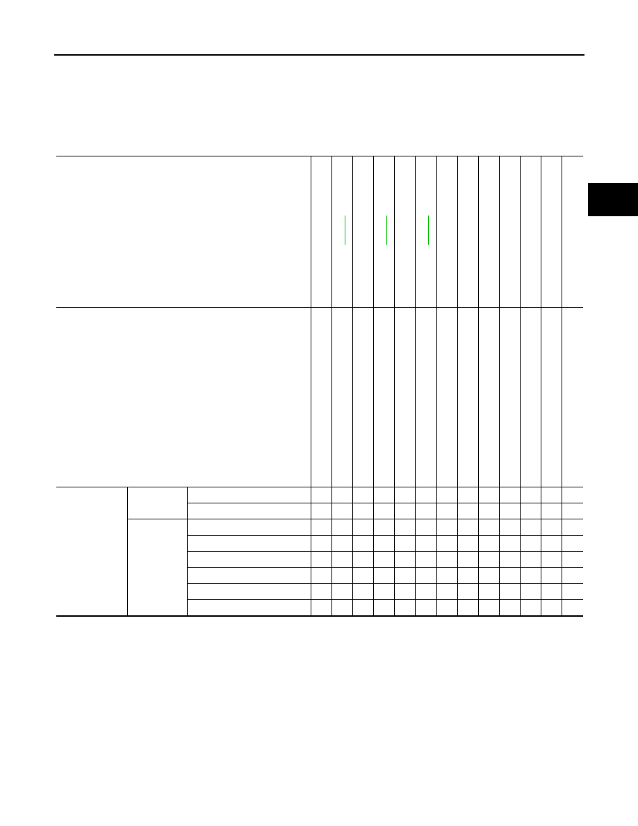
NVH Troubleshooting Chart
INFOID:0000000005248979
Use chart below to find the cause of the symptom. If necessary, repair or replace these parts.
×
: Applicable
Reference page
—
—
—
NV
H
in
F
A
X
an
d F
S
U s
ec
tio
ns
Re
fe
r
to
Fro
n
t axle in thi
s
ch
art.
NV
H in
WT se
cti
on
NV
H in
WT se
cti
on
Re
fe
r to
DRIVE S
H
A
FT i
n
t
h
is cha
rt.
NV
H
in
B
R
s
e
c
tio
n
NV
H
in
S
T
s
e
c
ti
o
n
Possible cause and SUSPECTED PARTS
Exc
e
ss
iv
e j
o
in
t a
n
g
le
Jo
in
t s
lid
in
g re
si
stan
ce
Im
ba
lan
c
e
Im
pro
per in
st
a
lla
ti
on
,
lo
os
en
es
s
Part
s interference
Whe
e
l be
ari
n
g
da
m
age
FRONT AXLE AND F
R
ONT
SUSPENSI
ON
FRONT AXL
E
TIRE
ROA
D
WHEEL
DRIVE SHA
F
T
BRAKE
STEERI
N
G
Symptom
DRIVE
SHAFT
Noise
×
×
×
×
×
×
×
×
×
Shake
×
×
×
×
×
×
×
×
×
FRONT
AXLE
Noise
×
×
×
×
×
×
×
×
×
Shake
×
×
×
×
×
×
×
×
×
Vibration
×
×
×
×
×
×
×
Shimmy
×
×
×
×
×
×
×
Judder
×
×
×
×
×
×
Poor quality ride or handling
×
×
×
×
×
Нет комментариевНе стесняйтесь поделиться с нами вашим ценным мнением.
Текст