Infiniti FX35, FX50 (S51). Manual — part 89
AV
STEERING SWITCH GROUND CIRCUIT
AV-129
< DTC/CIRCUIT DIAGNOSIS >
[WITHOUT NAVIGATION]
C
D
E
F
G
H
I
J
K
L
M
B
A
O
P
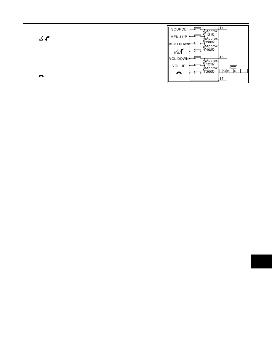
Standard
Between terminals 14 and 17
switch
ON
: Approx. 716 – 730
Ω
MENU DOWN switch ON
: Approx. 318 – 324
Ω
MENU UP switch ON
: Approx. 120 – 122
Ω
SOURCE switch ON
: Approx. 0
Ω
Between terminals 15 and 17
switch ON
: Approx. 318 – 324
Ω
VOL UP switch ON
: Approx. 120 – 122
Ω
VOL DOWN switch ON
: Approx. 0
Ω
JSNIA0216GB
AV-130
< SYMPTOM DIAGNOSIS >
[WITHOUT NAVIGATION]
MULTI AV SYSTEM SYMPTOMS
SYMPTOM DIAGNOSIS
MULTI AV SYSTEM SYMPTOMS
Symptom Table
INFOID:0000000005528292
OPERATION
RELATED TO HANDS-FREE PHONE
Simple Check for Bluetooth
™
Communication
If cellular phone and TEL adapter unit cannot be connected with Bluetooth
™
communication, following proce-
dure allows the technician to judge which device has malfunction.
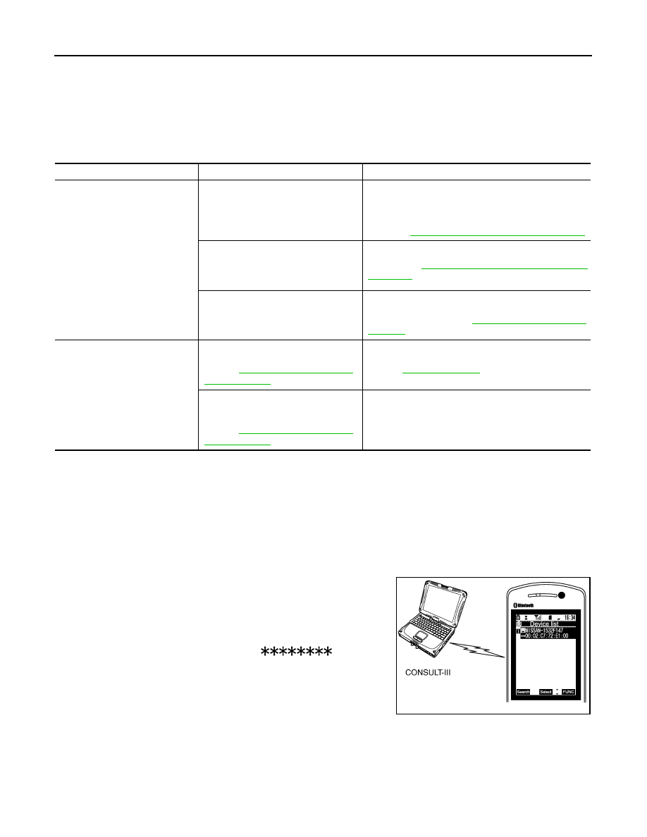
1.
Turn ON cellular phone, not connecting Bluetooth
™
communication.
2.
Start CONSULT-III, then start Windows
®
.
3.
Set CONSULT-III near a cellular phone.
4.
When operated Bluetooth
™
registration by cellular phone, check
if CONSULT-III
*
would be displayed on the device name.
(If other Bluetooth
™
device is located near cellular phone, a
name of the device would be displayed also.)
NOTE:
*:Displayed device name is “NISSAN-
”.
• If no device name is displayed, cellular phone is malfunctioning.
Repair the cellular phone first, then perform diagnosis.
• If CONSULT-III is displayed on device name, cellular phone is nor-
mal
*
. Perform diagnosis as per the following table.
*
: There is no 100% guarantee that cellular phone operates all
functions on AV control unit. Different phone manufacturers implement Bluetooth
™
in different ways. Phones
on Supported Phone List are tested and any minor exceptions are listed.
Symptoms
Check items
Probable malfunction location
Multifunction switch and preset
switch operation does not work.
• All switches cannot be operated.
• “MULTI AV” is displayed on system
selection screen when the CON-
SULT-III is started.
• Multifunction switch power supply and ground circuit.
• AV communication circuit between AV control unit and
multifunction switch.
Perform CONSULT-III self-diagnosis.
Refer to
AV-30, "CONSULT - III Function (MULTI AV)"
.
• All switches cannot be operated.
• “MULTI AV” is not displayed on sys-
tem selection screen when the CON-
SULT-III is initialized.
AV control unit power supply and ground circuit malfunc-
tion. Refer to
AV-101, "AV CONTROL UNIT : Diagnosis
.
Only specified switch cannot be operat-
ed.
Multifunction switch or preset switch malfunction.
Perform multifunction switch and preset switch self-di-
agnosis function. Refer to
.
Fuel economy display is abnor-
mal.
There is malfunction in the CONSULT-
III “self-diagnosis result” of “MULTI AV”.
Refer to
Perform detected DTC diagnosis.
Refer to
.
There is no malfunction in the CON-
SULT-III “self-diagnosis result” of
“MULTI AV”.
Refer to
Ignition signal circuit malfunction. (AV control unit)
JPNIA0441GB
AV
MULTI AV SYSTEM SYMPTOMS
AV-131
< SYMPTOM DIAGNOSIS >
[WITHOUT NAVIGATION]
C
D
E
F
G
H
I
J
K
L
M
B
A
O
P
RELATED TO CAMERA
RELATED TO RGB IMAGE
Symptoms
Check items
Probable malfunction location
Does not recognize cellular
phone connection. (No con-
nection is displayed on the dis-
play at the guide.)
Repeat the registration of cellular phone.
TEL adapter unit malfunction.
Refer to
Hands-free phone cannot be
established.
Both the reception and the speech cannot
be performed
• Perform CONSULT-III self-diagnosis.
AV-30, "CONSULT - III Function (MULTI AV)"
.
• No malfunction.
TEL adapter unit malfunction.
Refer to
• Malfunction is detected.
Perform detected DTC self-diagnosis.
Refer to
.
The other party's voice cannot
be heard by hands-free phone.
The operation of the “
” switch can
be performed.
TEL voice signal circuit malfunction between TEL adapt-
er unit and AV control unit.
The operation of the “
” switch can-
not be performed.
Control signal circuit.
Originating sound is not heard
by the other party with hands-
free phone communication.
Sound operation function is normal.
TEL adapter unit.
Refer to
.
Sound operation function does not work.
Microphone signal circuit malfunction.
Refer to
The system cannot be operat-
ed.
• The retractable hard top is fully closed.
• “SOURCE”, “MENU UP”, and “MENU
DOWN”, but “
” switches is not
operated.
Steering switch malfunction.
Replace steering switch.
Refer to
.
• The retractable hard top is fully closed.
• “SOURCE”, “MENU UP”, “MENU
DOWN”, and “
” switches of steer-
ing switch are not operated.
Steering switch signal B circuit malfunction.
Refer to
All steering switches do not work.
Steering switch ground circuit malfunction.
Refer to
Symptoms
Check items
Probable malfunction location
Camera image is not shown.
(Vehicle width and possible
route line is displayed.)
AUX image is displayed.
Camera image signal circuit.
Refer to
.
AUX image is not displayed.
Composite image signal circuit.
Refer to
.
Camera image is not shown.
(displayed in black and nothing
can be displayed)
—
• Horizontal synchronizing (HP) signal circuit malfunc-
tion between AV control unit and front display unit.
Refer to
• Vertical synchronizing (VP) signal circuit malfunction
between AV control unit and front display unit.
Refer to
Camera image does not switch.
“Reverse” is not turned ON on “Vehicle
Signals” screen of “Confirmation/Adjust-
ment”.
Reverse signal circuit malfunction.
“Reverse” is turned ON on “Vehicle Sig-
nals”screen of “Confirmation/Adjustment”.
AV control unit malfunction.
Replace AV control unit.
Refer to
AV-132
< SYMPTOM DIAGNOSIS >
[WITHOUT NAVIGATION]
MULTI AV SYSTEM SYMPTOMS
RELATED TO AUDIO
Symptoms
Check items
Possible malfunction location / Action to take
RGB image is not shown.
There is malfunction in the CONSULT-III
“self-diagnosis result” of “MULTI AV”.
Refer to
AV-30, "CONSULT - III Function
Perform detected DTC diagnosis.
Refer to
There is no malfunction in CONSULT-III
“self-diagnosis results” of “MULTI AV”.
Refer to
AV-30, "CONSULT - III Function
Vertical synchronizing (VP) signal circuit.
Refer to
.
Color of RGB image is not
proper.
Light blue (Cyan) tint.
RGB signal (R: red) circuit.
Refer to
.
Purple (Magenta) tint.
RGB signal (G: green) circuit.
Refer to
.
Screen looks yellowish.
RGB signal (B: blue) circuit.
Refer to
.
RGB screen is rolling.
—
RGB synchronizing signal circuit.
Refer to
.
Fuel economy display is mal-
functioning.
There is malfunction in the CONSULT-III
“self-diagnosis result” of “MULTI AV”.
Refer to
AV-30, "CONSULT - III Function
Perform detected DTC diagnosis.
Refer to
There is no malfunction in CONSULT-III
“self-diagnosis results” of “MULTI AV”.
Refer to
AV-30, "CONSULT - III Function
Ignition signal circuit malfunction. (AV control unit)
Symptoms
Check items
Probable malfunction location
The disk cannot be removed.
—
Disk eject signal circuit malfunction.
Refer to
.
Audio sound is not heard.
No sound from all speakers.
• Amp. ON signal circuit malfunction.
• BOSE amp. power supply and ground circuits malfunc-
AV-102, "BOSE AMP. : Diagnosis Procedure"
Sound is not heard from woofer.
• Woofer power supply and ground circuit malfunction.
• Sound signal (woofer) circuit malfunction.
• Woofer amp. ON signal circuit malfunction.
Sound is heard only from specific places.
Sound signals circuit of suspect system.
It does not change to “Driver's
Audio Stage” mode.
—
Mode change signal circuit.
Refer to
.
Satellite radio is not received.
There is malfunction in the CONSULT-III
self-diagnosis result.
Refer to
AV-30, "CONSULT - III Function
Perform detected DTC diagnosis.
Refer to
There is no malfunction in the CON-
SULT-III self-diagnosis result.
Perform the following inspection procedure.
1.
Check satellite radio antenna (antenna base)
mounting nut for looseness.
NOTE:
Tightening torque: 6.5 N-m (0.66 kg-m, 58 in-lb)
2.
Visually check for satellite radio antenna feeder.
The sound of satellite radio is
not heard.
Other audio sounds are normal.
Satellite radio sound signal circuit between AV control unit
and satellite radio tuner.
Нет комментариевНе стесняйтесь поделиться с нами вашим ценным мнением.
Текст