Infiniti FX35, FX50 (S51). Manual — part 87
AV
COMMUNICATION SIGNAL CIRCUIT (CONT-SAT)
AV-121
< DTC/CIRCUIT DIAGNOSIS >
[WITHOUT NAVIGATION]
C
D
E
F
G
H
I
J
K
L
M
B
A
O
P
COMMUNICATION SIGNAL CIRCUIT (CONT-SAT)
Description
INFOID:0000000005246842
Satellite radio tuner and AV control unit are connected with a serial communication. They transmit the opera-
tion signal from AV control unit to satellite radio tuner, and transmit the display signal from satellite radio tuner
to AV control unit.
Diagnosis Procedure
INFOID:0000000005246843
1.
CHECK CONTINUITY COMMUNICATION SIGNAL CIRCUIT
1.
Turn ignition switch OFF.
2.
Disconnect satellite radio tuner connector and AV control unit connector.
3.
Check continuity between satellite radio tuner harness connector and AV control unit harness connector.
4.
Check continuity between satellite radio tuner harness connector and ground.
Is the inspection result normal?
YES
>> GO TO 2.
NO
>> Repair harness or connector.
2.
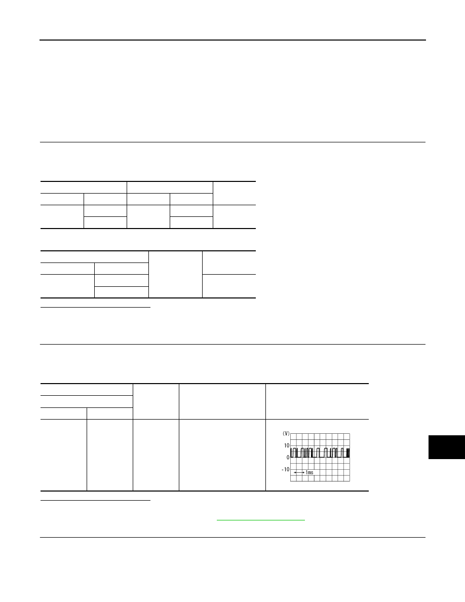
CHECK COMMUNICATION SIGNAL (SAT
→
CONT)
1.
Connect satellite radio tuner connector and AV control unit connector.
2.
Turn ignition switch ON.
3.
Check signal between satellite radio tuner harness connector and ground.
Is the inspection result normal?
YES
>> GO TO 3.
NO
>> Replace satellite radio tuner. Refer to
3.
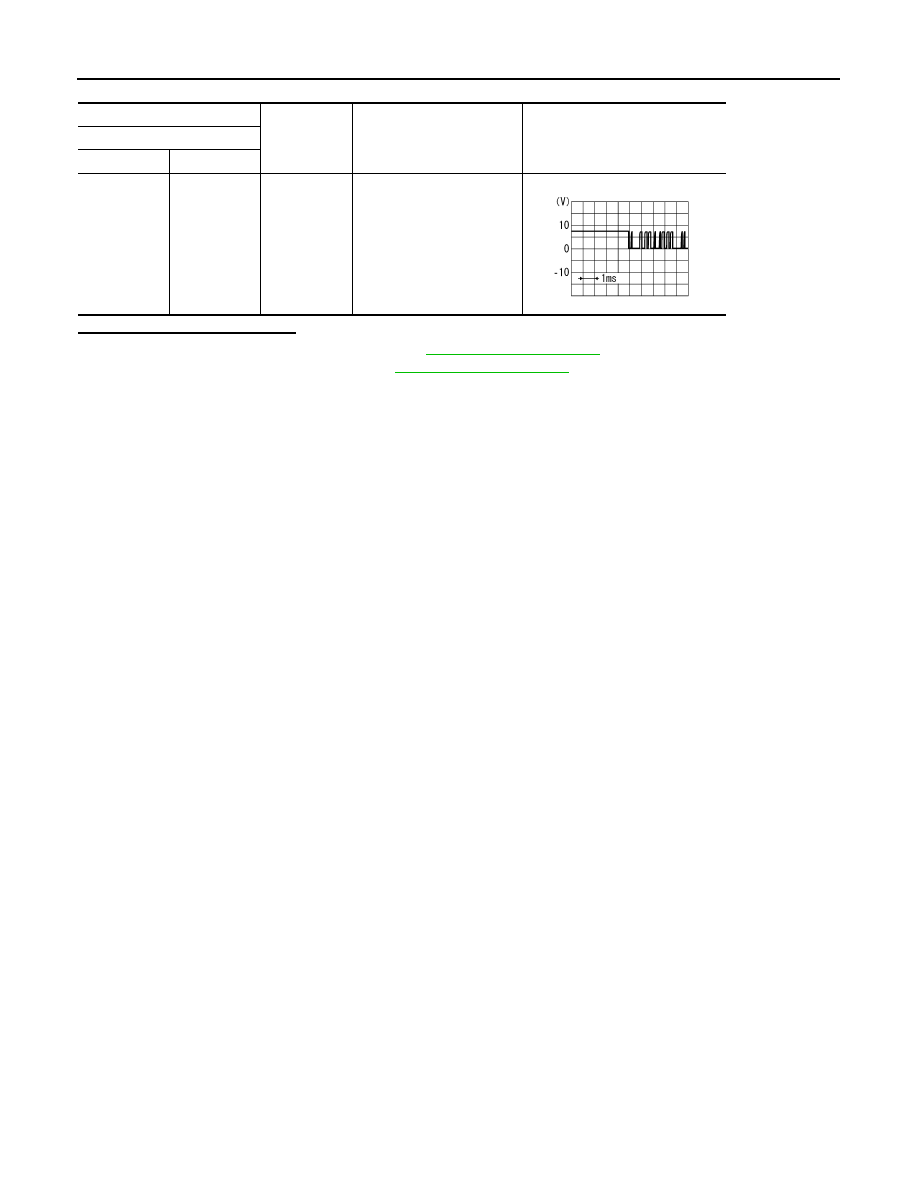
CHECK COMMUNICATION SIGNAL (CONT
→
SAT)
Check signal between satellite radio tuner harness connector and ground.
Satellite radio tuner
AV control unit
Continuity
Connector
Terminals
Connector
Terminals
B236
9
M206
130
Existed
10
122
Satellite radio tuner
Ground
Continuity
Connector
Terminals
B236
9
Not existed
10
(+)
(
−
)
Condition
Reference value
Satellite radio tuner
Connector
Terminal
B236
9
Ground
When satellite radio mode is
selected.
SKIA9300J
AV-122
< DTC/CIRCUIT DIAGNOSIS >
[WITHOUT NAVIGATION]
COMMUNICATION SIGNAL CIRCUIT (CONT-SAT)
Is the inspection result normal?
YES
>> Replace satellite radio tuner. Refer to
NO
>> Replace AV control unit. Refer to
(+)
(
−
)
Condition
Reference value
Satellite radio tuner
Connector
Terminal
B236
10
Ground
When satellite radio mode is
selected.
SKIA9301J
AV
REQUEST SIGNAL CIRCUIT (SAT
→
CONT)
AV-123
< DTC/CIRCUIT DIAGNOSIS >
[WITHOUT NAVIGATION]
C
D
E
F
G
H
I
J
K
L
M
B
A
O
P
REQUEST SIGNAL CIRCUIT (SAT
→
CONT)
Description
INFOID:0000000005246844
Request signal transmits the signal to recognize the connection of satellite radio tuner from satellite radio
tuner to AV control unit.
Diagnosis Procedure
INFOID:0000000005246845
1.
CHECK CONTINUITY REQUEST SIGNAL CIRCUIT
1.
Turn ignition switch OFF.
2.
Disconnect satellite radio tuner connector and AV control unit connector.
3.
Check continuity between satellite radio tuner unit harness connector and AV control unit harness connec-
tor.
4.
Check continuity between satellite radio tuner harness connector and ground.
Is the inspection result normal?
YES
>> GO TO 2.
NO
>> Repair harness or connector.
2.
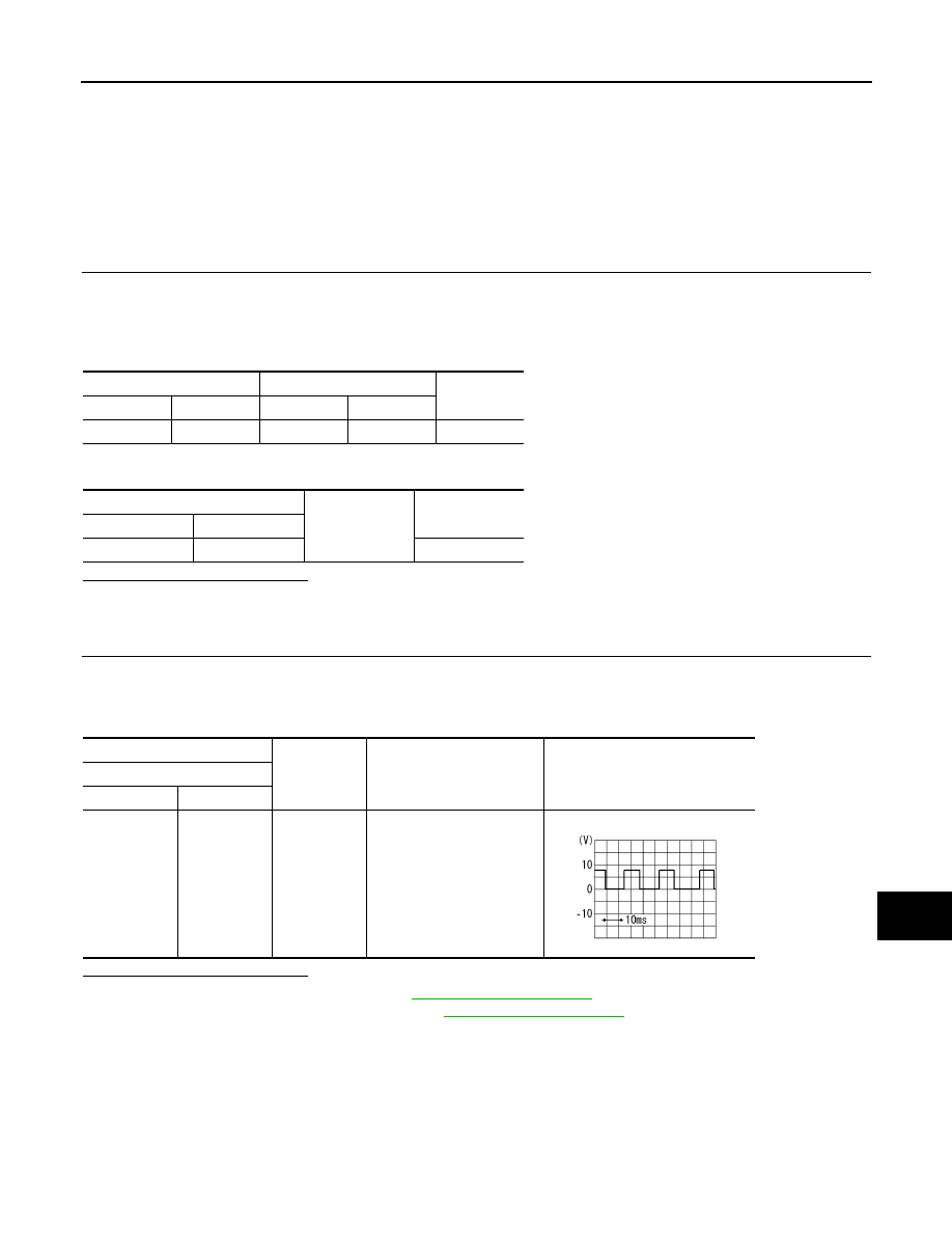
CHECK COMMUNICATION SIGNAL
1.
Connect satellite radio tuner connector and AV control unit connector.
2.
Turn ignition switch ON.
3.
Check signal between satellite radio tuner harness connector and ground.
Is the inspection result normal?
YES
>> Replace AV control unit. Refer to
NO
>> Replace satellite radio tuner. Refer to
Satellite radio tuner
AV control unit
Continuity
Connector
Terminal
Connector
Terminal
B236
8
M206
129
Existed
Satellite radio tuner
Ground
Continuity
Connector
Terminal
B236
8
Not existed
(+)
(
−
)
Condition
Reference value
Satellite radio tuner
Connector
Terminal
B236
8
Ground
When satellite radio mode is
selected.
SKIA9299J
AV-124
< DTC/CIRCUIT DIAGNOSIS >
[WITHOUT NAVIGATION]
STEERING SWITCH SIGNAL A CIRCUIT
STEERING SWITCH SIGNAL A CIRCUIT
Description
INFOID:0000000005530041
Transmits the steering switch signal to AV control unit.
Diagnosis Procedure
INFOID:0000000005530042
1.
CHECK STEERING SWITCH SIGNAL A CIRCUIT
1.
Disconnect AV control unit connector and spiral cable connector.
2.
Check continuity between AV control unit harness connector and spiral cable harness connector.
3.
Check continuity between AV control unit harness connector and ground.
Is the inspection result normal?
YES
>> GO TO 2.
NO
>> Repair harness or connector.
2.
CHECK SPIRAL CABLE
Check spiral cable.
Is the inspection result normal?
YES
>> GO TO 3.
NO
>> Replace spiral cable. Refer to
3.
CHECK AV CONTROL UNIT VOLTAGE
1.
Connect AV control unit connector and spiral cable connector.
2.
Turn ignition switch ON.
3.
Check voltage between AV control unit harness connector.
Is the inspection result normal?
YES
>> GO TO 4.
NO
>> Replace AV control unit. Refer to
4.
CHECK STEERING SWITCH
1.
Turn ignition switch OFF.
2.
Check steering switch. Refer to
AV-124, "Component Inspection"
Is the inspection result normal?
YES
>> INSPECTION END
NO
>> Replace steering switch. Refer to
Component Inspection
INFOID:0000000005530059
Measure the resistance between the steering switch connector terminals 14 to 17 and 15 to 17.
AV control unit
Spiral cable
Continuity
Connector
Terminal
Connector
Terminal
M201
6
M36
24
Existed
AV control unit
Ground
Continuity
Connector
Terminal
M201
6
Not existed
(+)
(
−
)
Voltage
(Approx.)
AV control unit
AV control unit
Connector
Terminal
Connector
Terminal
M201
6
M201
15
3.3 V
Нет комментариевНе стесняйтесь поделиться с нами вашим ценным мнением.
Текст