Infiniti FX35, FX50 (S51). Manual — part 101
AV
DIAGNOSIS SYSTEM (AV CONTROL UNIT)
AV-177
< SYSTEM DESCRIPTION >
[NAVIGATION (SINGLE MONITOR)]
C
D
E
F
G
H
I
J
K
L
M
B
A
O
P
1.
Start the self-diagnosis function and select “Self Diagnosis”.
-
Self-diagnosis subdivision screen is displayed, and the self-diagnosis mode starts.
-
The bar graph visible on the center of the self-diagnosis subdivision screen indicates progress of the trou-
ble diagnosis.
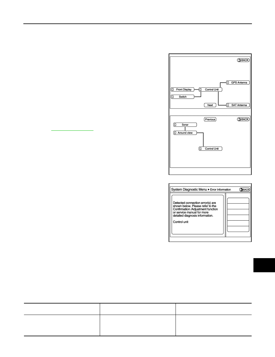
2.
Diagnosis results are displayed after the self-diagnosis is com-
pleted. The unit names and the connection lines are color-coded
according to the diagnostic results.
NOTE:
Control unit (AV control unit) is displayed in red.
• Replace AV control unit if “Self-Diagnosis did not run because of a control
unit malfunction” is indicated. The symptom is AV control unit internal error.
Refer to
.
• If multiple errors occur at the same time for a single unit, the screen switch
colors are determined according to the following order of priority: red > gray.
-
The comments of the self-diagnosis results can be viewed with a
component in the diagnosis result screen.
Detection Range of Self-diagnosis Mode
• The self-diagnosis mode allows the technician to diagnose the connection in the communication line
between AV control unit and each unit and the internal operation of the AV control unit.
• Because the start condition of diagnosis function is a switch operation, the on board diagnosis function can-
not be started up if any malfunction is detected in the communication circuit between AV control unit and
multifunction switch.
SELF-DIAGNOSIS RESULTS
Check the applicable display at the following table, and then repair the malfunctioning parts.
Only Unit Part Is Displayed In Red.
Diagnosis results
Unit
Connec-
tion line
Normal
Green
Green
Connection malfunction
Gray
Yellow
Unit malfunction
Note
Red
Green
JSNIA2496ZZ
JPNIA1787ZZ
Screen switch
Description
Possible malfunction location / Action to
take
Control Unit
Malfunction is detected in AV control unit
power supply and ground circuits.
Check AV control unit power supply and
ground circuits. When detecting no mal-
function in those components, replace AV
control unit.
AV-178
< SYSTEM DESCRIPTION >
[NAVIGATION (SINGLE MONITOR)]
DIAGNOSIS SYSTEM (AV CONTROL UNIT)
A Connecting Cable Between Units Is Displayed In Yellow.
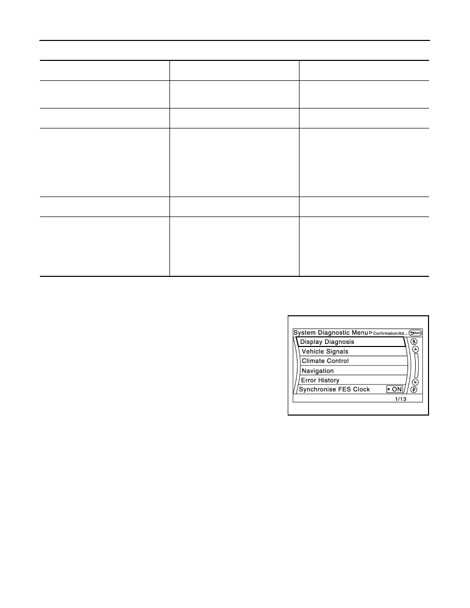
CONFIRMATION/ADJUSTMENT MODE
1.
Start the diagnosis function and select “Confirmation/Adjustment”. The confirmation/adjustment mode
indicates where each item can be checked or adjusted.
2.
Select each switch on the “Confirmation/Adjustment Mode”
screen to display the relevant trouble diagnosis screen. Press
the “Back” switch to return to the initial Confirmation/Adjustment
Mode screen.
Area with yellow connection lines
Description
Possible malfunction location / Action to
take
Control unit
⇔
Front Display
Malfunction is detected in serial communi-
cation circuits between AV control unit and
front display unit.
Serial communication circuits between AV
control unit and front display unit.
Control unit
⇔
GPS Antenna
GPS antenna connection malfunctions de-
tected.
GPS antenna
Control unit
⇔
Around view
When either one of the following items are
detected:
• around view monitor control unit power
supply and ground circuits are malfunc-
tioning.
• AV communication circuits between
around view monitor control unit and
multifunction switch are malfunctioning.
• Around view monitor control unit power
supply and ground circuits.
• AV communication circuits between
around view monitor control unit and
multifunction switch.
Control unit
⇔
SAT Antenna
Satellite radio antenna connection malfunc-
tion is detected.
Satellite radio antenna disconnection
Around view
⇔
Sonar
When either one of the following items are
detected:
• sonar control unit power supply and
ground circuits are malfunctioning.
• AV communication circuits between AV
control unit and sonar control unit are
malfunctioning.
• Sonar control unit power supply and
ground circuits.
• AV communication circuits between AV
control unit and sonar control unit.
JSNIA2175ZZ
AV
DIAGNOSIS SYSTEM (AV CONTROL UNIT)
AV-179
< SYSTEM DESCRIPTION >
[NAVIGATION (SINGLE MONITOR)]
C
D
E
F
G
H
I
J
K
L
M
B
A
O
P
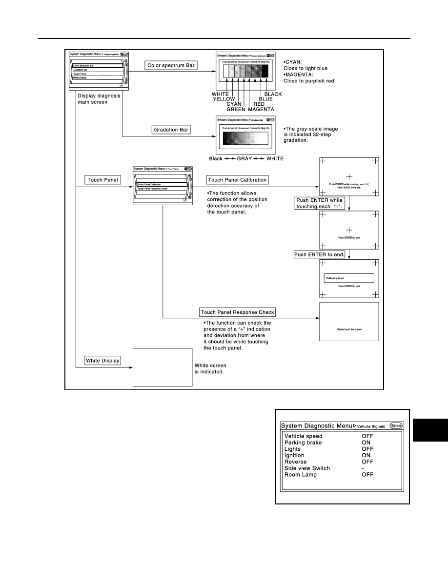
Display Diagnosis
Vehicle Signals
A comparison check can be made of each actual vehicle signal and
the signals recognized by the system.
JSNIA2176GB
JSNIA2177ZZ
AV-180
< SYSTEM DESCRIPTION >
[NAVIGATION (SINGLE MONITOR)]
DIAGNOSIS SYSTEM (AV CONTROL UNIT)
Climate Control
Refer to “HEATER & AIR CONDITIONING CONTROL SYSTEM” for details.
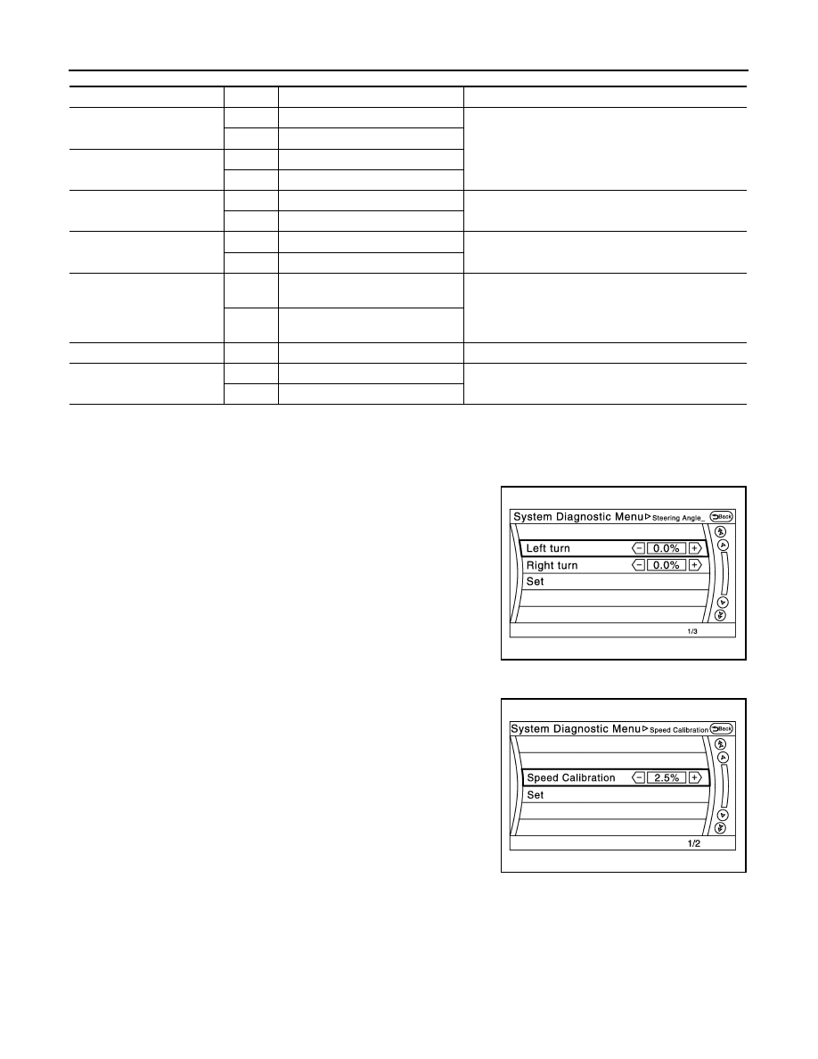
Navigation
STEERING ANGLE ADJUSTMENT
The steering angle output value detected with the gyroscope is
adjusted.
SPEED CALIBRATION
During normal driving, distance error caused by tire wear and tire
pressure change is automatically adjusted for by the automatic dis-
tance correction function. This function, on the other hand, is for
immediate adjustment, in cases such as driving with tire chain fitted
on tires.
Error History
The self-diagnosis results are judged depending on whether any error occurs from when “Self-diagnosis” is
selected until the self-diagnosis results are displayed.
However, the diagnosis results are judged normal if an error has occurred before the ignition switch is turned
ON and then no error has occurred until the self-diagnosis start. Check the “Error Record” to detect any error
that may have occurred before the self-diagnosis start because of this situation.
The error record displays the time and place of the most recent occurrence of that error. However, take note of
the following points.
Diagnosis item
Display
Vehicle status
Remarks
Vehicle speed
ON
Vehicle speed > 0 km/h (0 MPH)
Changes in indication may be delayed. This is normal.
OFF
Vehicle speed = 0 km/h (0 MPH)
Parking brake
ON
Parking brake is applied.
OFF
Parking brake is released.
Lights
ON
Light switch ON
—
OFF
Light switch OFF
Ignition
ON
Ignition switch ON
—
OFF
Ignition switch in ACC position
Reverse
ON
Shift the selector lever to “R” posi-
tion
Changes in indication may be delayed. This is normal.
OFF
Shift the selector lever other than
“R” position
SIDE VIEW SW
—
—
This item is displayed, but cannot be monitored.
ROOM LAMP
ON
After opening any door; 5 seconds.
Check 10 seconds later, after closing all doors.
OFF
Except for above.
JSNIA2179ZZ
JSNIA2180ZZ
Нет комментариевНе стесняйтесь поделиться с нами вашим ценным мнением.
Текст