Infiniti FX35, FX50 (S51). Manual — part 100

AV
SYSTEM
AV-173
< SYSTEM DESCRIPTION >
[NAVIGATION (SINGLE MONITOR)]
C
D
E
F
G
H
I
J
K
L
M
B
A
O
P
• Sonar control unit has the diagnosis function. It can detect the corner sensor malfunction or sensor harness
open circuit. It transmits the diagnosis results to around view monitor control unit and always displays the
sonar indicator in red to inform the user.
Obstacle Detection Distance
• Sonar control unit changes the outputs of the sonar indicator and warning buzzer in 3 stages according to
the obstacle detection distance from the corner sensor.
• The sonar control unit can change the setting of obstacle detection distance in 4 stages.
Obstacle detection image
Detection distance
Sonar Indicator Display
• Around view monitor control unit that receives the detection signal and detection distance signal from sonar
control unit displays the sonar indicator on display.
• Around view monitor control unit changes the color or blinking cycle of the indicator according to the detec-
tion distance.
JSNIA1430ZZ
A.
Approx. 50 cm (19.6 in)
B.
Approx. 15 cm (5.9 in)
Warning item
Sensitivity level 1
(Faster warning)
Sensitivity level 2
(Default value)
Sensitivity level 3
(Slower warning)
Sensitivity level 4
(Slowest warning)
First stage
warning
70 – 80 cm (27.5 – 31.4 in)
60 – 70 cm (23.6 – 27.5 in)
50 – 60 cm (19.6 – 23.6 in)
40 – 50 cm (15.7 – 19.6 in)
Second stage
warning
50 – 70 cm (19.6 – 27.5 in)
40 – 60 cm (15.7 – 23.6 in)
30 – 50 cm (11.8 – 19.6 in)
30 – 40 cm (11.8 – 15.7 in)
Third stage
warning
Less than 50 cm (19.6 in)
Less than 40 cm (15.7 in)
Less than 30 cm (11.8 in)
Less than 30 cm (11.8 in)

AV-174
< SYSTEM DESCRIPTION >
[NAVIGATION (SINGLE MONITOR)]
SYSTEM
Color and blinking cycle of sonar indicator
Sonar Buzzer Operation
• Each sonar sensor transmits a sensor signal to the sonar control unit when detecting an obstacle.
• The sonar control unit converts a signal received from each sonar sensor into distance and transmits detec-
tion distance signal to the AV control unit via AV communication.
• The AV control unit transmits a buzzer signal to the BOSE amp. corresponding to each sonar sensor based
on the received signal.
• When receiving a buzzer signal, the BOSE amp. transmits the buzzer signal to the each speaker. When
each speaker receives a buzzer signal, a buzzer sounds.
• When the front corner sensor detects an obstacle, a buzzer is heard from the speakers on the front side.
• When the rear corner sensor detects an obstacle, a buzzer is heard from the speakers on the rear side.
• It changes the buzzer cycle in 3 stages according to the detection distance.
Sonar buzzer cycle
VEHICLE INFORMATION FUNCTION
• Status of audio, climate control system, fuel economy, maintenance and navigation are displayed.
• AV control unit displays the fuel consumption status while receiving data signal through CAN communication
from ECM, unified meter and A/C amp.
• AV control unit is connected to BCM via CAN communication transmitting/receiving for the vehicle settings
function.
JSNIA1100GB
JSNIA1101GB
AV
DIAGNOSIS SYSTEM (AV CONTROL UNIT)
AV-175
< SYSTEM DESCRIPTION >
[NAVIGATION (SINGLE MONITOR)]
C
D
E
F
G
H
I
J
K
L
M
B
A
O
P
DIAGNOSIS SYSTEM (AV CONTROL UNIT)
On Board Diagnosis Function
INFOID:0000000005475012
MULTIFUNCTION SWITCH AND PRESET SWITCH SELF-DIAGNOSIS FUNCTION
The ON/OFF operation (continuity) of each switch in the multifunction switch and preset switch can be
checked.
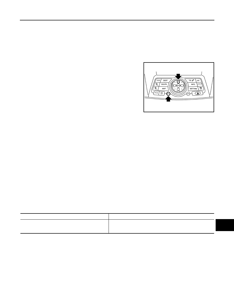
Self-diagnosis Mode
• Press the “BACK” switch and the “UP” switch of the 8-direction
switches within 10 seconds after turning the ignition switch from
OFF to ACC and hold them for 3 seconds or more. Then the
buzzer sounds, all indicators of the preset switch illuminate, and
the self-diagnosis mode starts.
• The continuity of each switch at the ON position can be checked
by pressing the switch. The buzzer sounds if the switch is normal.
NOTE:
The hazard switch and disk eject switch cannot be checked.
Finishing Self-diagnosis Mode
Self-diagnosis mode is canceled when turning the ignition switch OFF.
MULTI AV SYSTEM ON BOARD DIAGNOSIS FUNCTION
• The AV control unit diagnosis function starts up with multifunction switch operation and the AV control unit
performs a diagnosis for each unit in the system during the on board diagnosis.
• Perform a CONSULT-III diagnosis if the on board diagnosis does not start, e.g., the screen does not display
anything, the multifunction switch does not function, etc.
ON BOARD DIAGNOSIS
Description
• The trouble diagnosis function has a self-diagnosis mode for conducting trouble diagnosis automatically and
a confirmation/adjustment mode for operating manually.
• The self-diagnosis mode performs diagnoses on the AV control unit, connections between system compo-
nents as well as connections between AV control unit and GPS antenna. Then it displays the diagnosis
results on the display.
• The confirmation/adjustment mode allows the technician to check, modify or adjust the vehicle signals and
set values, as well as to monitor the system error records and system communication status. The checking,
modifying or adjusting generally require human intervention and judgment (the system cannot make judg-
ment automatically).
On Board Diagnosis Item
JSNIA2171ZZ
Mode
Description
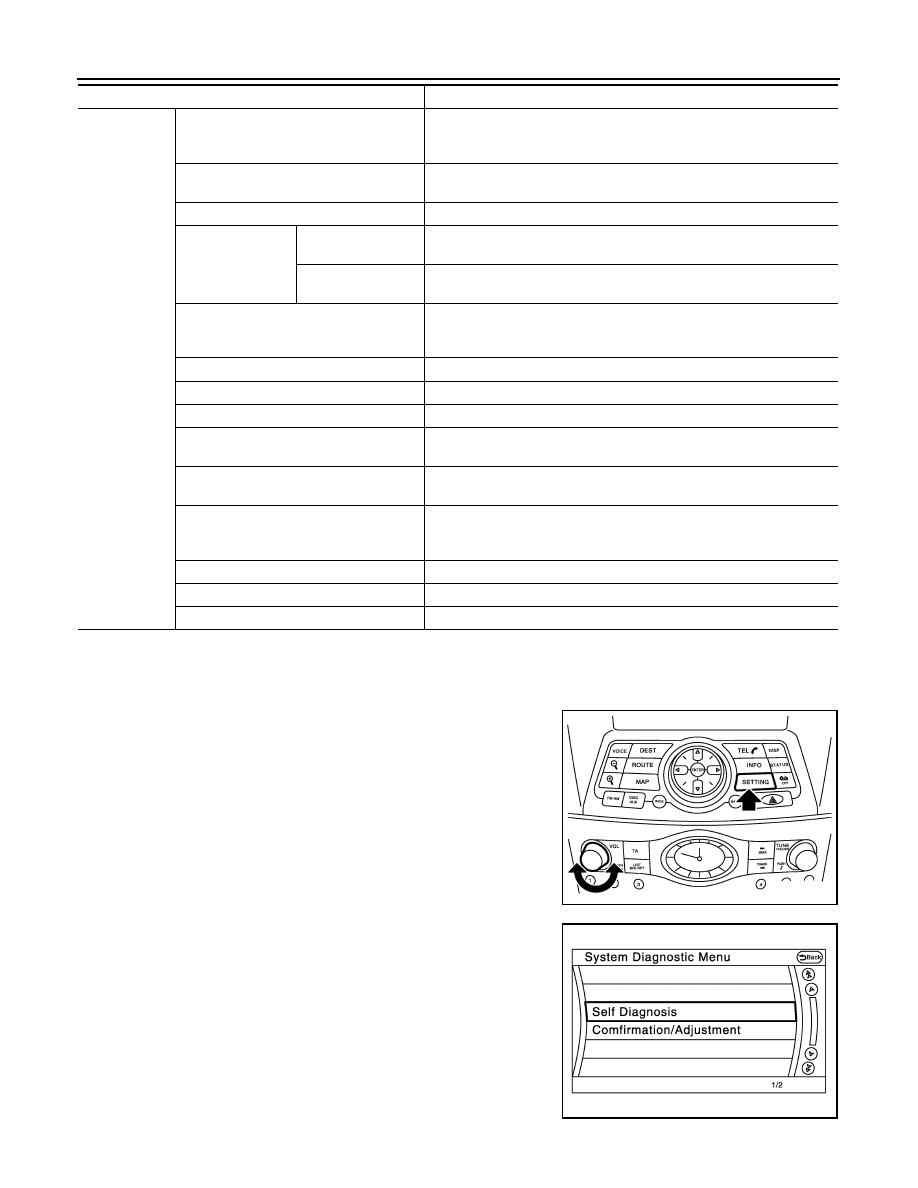
Self Diagnosis
• AV control unit diagnosis.
• Diagnoses the connections across system components, between AV
control unit and GPS antenna.
AV-176
< SYSTEM DESCRIPTION >
[NAVIGATION (SINGLE MONITOR)]
DIAGNOSIS SYSTEM (AV CONTROL UNIT)
STARTING PROCEDURE
1.
Start the engine.
2.
Turn the audio system OFF.
3.
While pressing the “SETTING” button, turn the volume control
dial clockwise or counterclockwise for 40 clicks or more. (When
the self-diagnosis mode is started, a short beep will be heard.)
• Shifting from current screen to previous screen is performed
by pressing “BACK” button.
4.
The trouble diagnosis initial screen is displayed, and then the
items of “Self Diagnosis” and “Confirmation/Adjustment” can be
selected.
SELF-DIAGNOSIS MODE
Confirmation/
Adjustment
Display Diagnosis
The following check functions are available: color tone check by color
bar display and white display, light and shade check by gray scale dis-
play and touch panel calibration response check.
Vehicle Signals
Diagnosis of signals can be performed for vehicle speed, parking brake,
lights, ignition, reverse, side view switch and room lamp.
Climate Control
Start auto air conditioner system self-diagnosis.
Navigation
Steering Angle Ad-
justment
When there is a difference between the actual turning angle and the ve-
hicle mark turning angle, it can be adjusted.
Speed Calibration
When there is a difference between the current location mark and the ac-
tual location, it can be adjusted.
Error History
The system malfunction and the frequency when occurring in the past
are displayed. When the malfunctioning item is selected, the time and
place that the selected malfunction last occurred are displayed.
Synchronizer FES Clock
–
Speaker Test
The connection of a speaker can be confirmed by test tone.
Vehicle CAN Diagnosis
The transmitting/receiving of CAN communication can be monitored.
AV COMM Diagnosis
The communication condition of each unit of Multi AV system can be
monitored.
Hands-free Phone
The received volume adjustment of hands-free phone, microphone
speaker check, and erase memory can be performed.
Camera Cont.
It can perform the confirmation of a signal connection to around view
monitor control unit, the calibration of each camera, Correct Draw Line
of Camera Image, and Fine Tuning of Birds-Eye View.
Delete Unit Connection Log
Erase the connection history of unit and error history.
Initialize Settings
Initializes the AV control unit memory.
Version Information
Version information of the AV control unit is displayed.
Mode
Description
JSNIA2172ZZ
JSNIA2173ZZ
Нет комментариевНе стесняйтесь поделиться с нами вашим ценным мнением.
Текст